Method and device for the electrolytic treatment of electrically conducting structures which are insulated from each other and positioned on the surface of electrically insulating film materials and use of the method

Inactive Publication Date: 2005-12-27
ATOTECH DEUT GMBH
View PDF14 Cites 17 Cited by
  • Summary
  • Abstract
  • Description
  • Claims
  • Application Information

AI Technical Summary

Benefits of technology

[0082]In order to prevent metal deposition on the cathodically polarised electrodes, these can be screened with ion-sensitive membranes so that electrolytic spaces are formed which surround the cathodically polarised electrodes. If ion-sensitive membranes are not used, deposited metal on the cathodically polarised electrodes must be removed again on a daily or weekly basis. For this purpose, for example a cathodically polarised surface electrode can be disposed for stripping these electrodes, the metallised electrodes bein

Problems solved by technology

A fundamental disadvantage of the above-mentioned methods resides in the fact that only whole-surface conductive surfaces can be electrolytically treated but not electrically mutually insulated structures.
This device has the disadvantage that the brushes are completely covered with metal within a very short time since approximately 90% of the metal is deposited on the brushes and only 10% on the regions to be metallised.
In addition, the brush ends can easily damage fine structures on the printed circuit boards.
Likewise, the brush material thereby wears quickly, the finest particles being rubbed off and getting into the bath where they lead to damage during metallisation.
These wear especially quickly.
Particles which come from the worn

Method used


Image

  • Method and device for the electrolytic treatment of electrically conducting structures which are insulated from each other and positioned on the surface of electrically insulating film materials and use of the method
  • Method and device for the electrolytic treatment of electrically conducting structures which are insulated from each other and positioned on the surface of electrically insulating film materials and use of the method
  • Method and device for the electrolytic treatment of electrically conducting structures which are insulated from each other and positioned on the surface of electrically insulating film materials and use of the method

Examples


Embodiment Construction

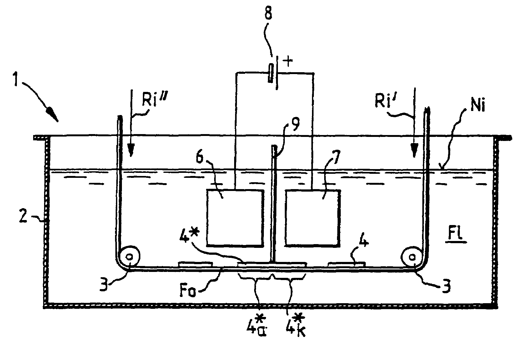
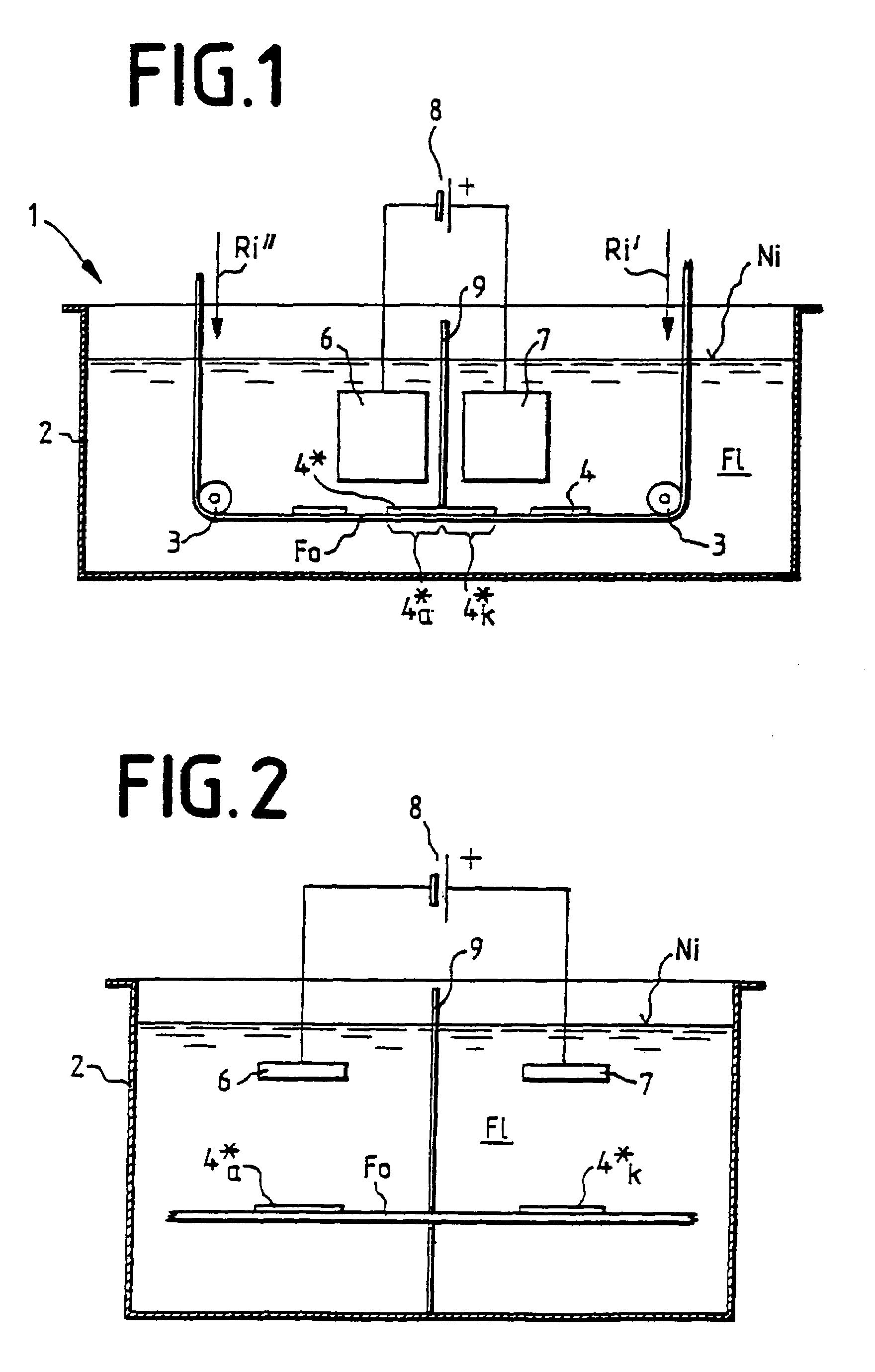
[0017]In order to implement the method according to the invention, the foil material is unloaded from a store, for example a roller (for example unwound), then transported on a conveying line through a treatment unit and brought thereby in contact with treatment fluid. After passing through the unit, the foil material is finally loaded (for example wound) once again onto a store, for example a roller. One possibility consists in transporting the material in a horizontal conveying direction. The conveying line shown in the drawings as flat and horizontal could, if desired, be vertical. Such an arrangement is implemented in so-called reel-to-reel units. For this purpose, the material is transported by known means, for example by rollers or cylinders. Alternatively, the foil material can also be guided in the unit via deflecting rollers and as a result can change the direction in the unit one or more times. As a result, the longest possible route in the unit is attained so that the tre...


PUM

PropertyMeasurementUnit
Timeaaaaaaaaaa
Angleaaaaaaaaaa
Electrical conductivityaaaaaaaaaa

Abstract

For electrolytic treatment of electrically mutually insulated, electrically conductive structures 4 on surfaces of electrically insulating foil material (Fo), is unloaded from a store 15′, 15″, transported on a conveying line through a treatment unit 1 and brought in contact with treatment fluid F1. During transportation, the material Fo is guided past at least one electrode arrangement, having at least one cathodically polarised electrode 6 and at least one anodically polarised electrode 7, both being brought in contact with the treatment fluid F1 and being connected to a current/voltage source 8. Current flows through the electrodes 6, 7 and the electrically conductive structures 4. The electrodes 6, 7 are screened from each other so that substantially no electric current is able to flow directly between oppositely polarised electrodes 6, 7. The material Fo is finally loaded back onto a store 15′, 15″.

Description

BACKGROUND OF THE INVENTION[0001]1. Field of the Invention[0002]The invention relates to a method and device for electrolytic treatment of electrically mutually insulated, electrically conductive structures on surfaces of electrically insulating foil material and applications of the method.[0003]2. Description of the Related Art[0004]Electroplating processes among others are used for metal coating of strips. For quite a number of years, so-called reel-to-reel treatment units have been used for this purpose, the material being transported through said units and, during transportation, coming into contact with treatment fluid.[0005]A method for electrolytic etching of aluminium foil is described in U.S. Pat. No. 3,779,877 in which the foil is firstly guided over anodically polarised contact shoes and then guided into the electroplating treatment baths. In the treatment baths, the foil is guided past cathodically polarised electrodes and then taken out of the bath again. The foil is th...

Claims


Application Information

Patent Timeline
IPC IPC(8): C25D5/00C25D5/18C25D7/06C25D17/00C25D19/00C25F3/02C25F7/00H05K3/07H05K3/24
CPCC25D7/0614C25F3/02C25F7/00H05K3/241C25D17/008C25D7/0635H05K3/07
Inventor HUBEL, EGON
Owner ATOTECH DEUT GMBH
Why Eureka
Try Eureka