Adaptive method and apparatus to control loop bandwidth of a phase lock loop

a phase lock loop and adaptive control technology, applied in the direction of electrical equipment, oscillator generators, pulse automatic control, etc., can solve the problems of reduced bandwidth, increased lock-in-time of the pll, and noise in the reference signal

Inactive Publication Date: 2005-12-27
IBM CORP
View PDF9 Cites 59 Cited by
  • Summary
  • Abstract
  • Description
  • Claims
  • Application Information

AI Technical Summary

Problems solved by technology

In the majority of PLL systems, there is an inherent tradeoff between reducing ‘lock in time’ and jitter that results from noise in the reference signal.
However, reduced bandwidth implies an increase in lock-in-time of the PLL.
There are also various complicated or otherwise unwieldy techniques for adaptively changing loop bandwidth parameters.

Method used


Image

  • Adaptive method and apparatus to control loop bandwidth of a phase lock loop
  • Adaptive method and apparatus to control loop bandwidth of a phase lock loop
  • Adaptive method and apparatus to control loop bandwidth of a phase lock loop

Examples


Embodiment Construction

[0015]In the following discussion, numerous specific details are set forth to provide a thorough understanding of the present invention. However, those skilled in the art will appreciate that the present invention may be practiced without such specific details. In other instances, well-known elements have been illustrated in schematic or block diagram form in order not to obscure the present invention with unnecessary detail.

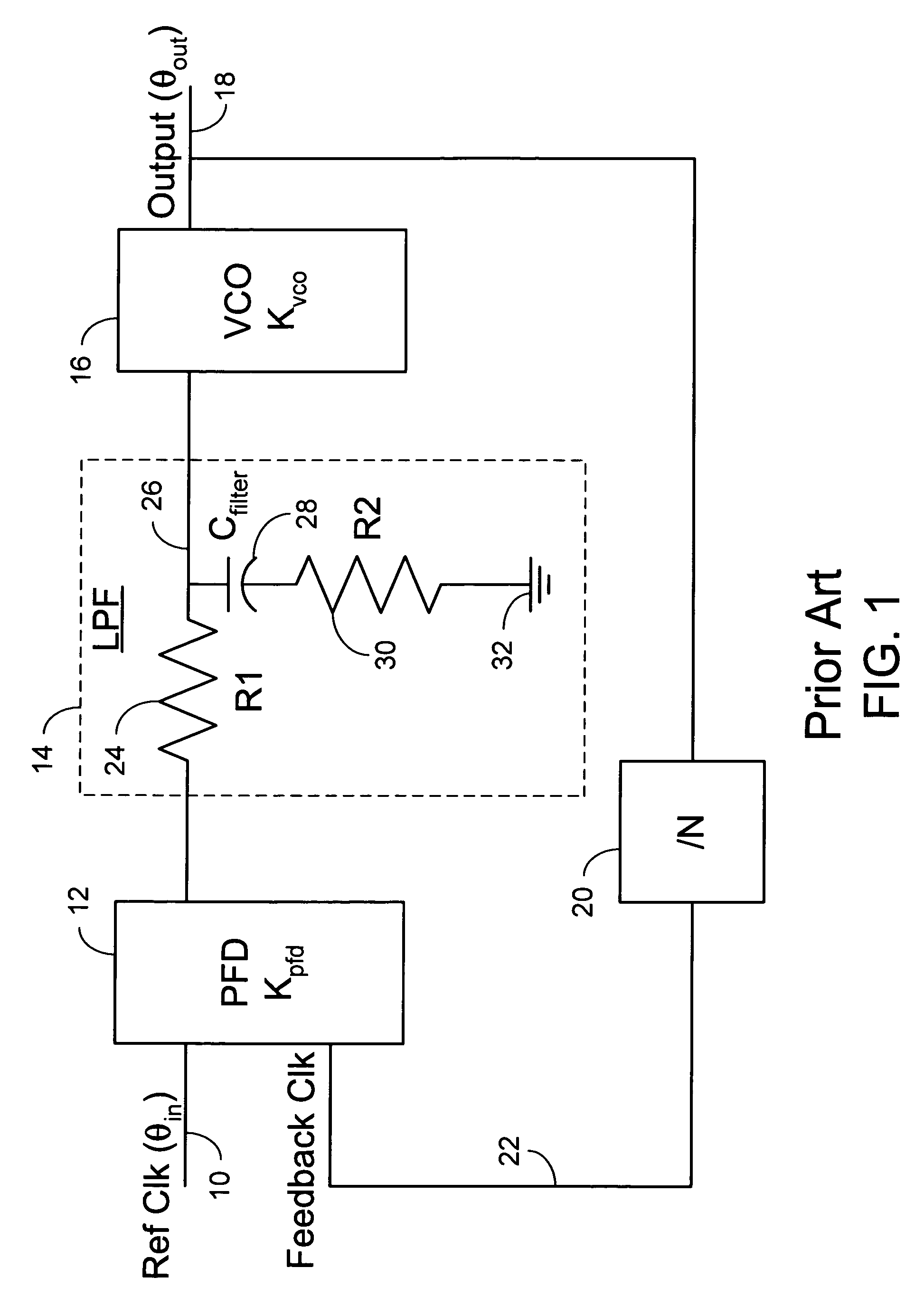
[0016]In FIG. 1, a reference clock signal is applied on a lead 10 to a first input of a PFD (Phase / Frequency Detector) 12. An LPF (Low Pass Filter) 14 is connected between an output of PFD 12 and an input of a VCO (Voltage Controlled Oscillator) 16. Although not required, the frequency of an output signal at an output lead 18 of the VCO is a multiple (or sub multiple) of the reference frequency signal applied on lead 10. Thus a frequency divider or adjuster 20 is used to revise the frequency of the signal on lead 18 to a frequency which is the same as the refere...


PUM


Abstract

Disclosed is a PLL (Phase Lock Loop) reducing the lock-in-time of the phase lock loop by altering the impedance of the damping resistor portion of the included LPF (Low Pass Filter) as a function of the difference in frequency or phase between a PLL applied reference frequency and the output frequency provided by the VCO (Voltage Controlled Oscillator) portion of the PLL. This variable impedance is accomplished by introducing a feed forward path that switches a capacitor in and out of the circuit in accordance with the difference frequency. One embodiment uses a mixer to provide the difference frequency signal.

Description

TECHNICAL FIELD[0001]The invention relates to adaptive control of the loop bandwidth of a PLL (Phase Lock Loop).BACKGROUND[0002]In the majority of PLL systems, there is an inherent tradeoff between reducing ‘lock in time’ and jitter that results from noise in the reference signal. A narrow band width attenuates small noise from the reference / input signal, thereby resulting in reduced noise and induced jitter at the output. However, reduced bandwidth implies an increase in lock-in-time of the PLL. There have been many approaches used to reducing lock-in-time of PLLs. These include digital / DSP (Digital Signal Processing) methods, dual loop / PLL architectures, feed forward compensation techniques, and variable loop bandwidth methods. In the DSP method, the phase error is fed in to a ‘fast DSP processor’ whose output is then used to adjust the center operating frequency of a VCO (Voltage Controlled Oscillator). Once the error is reduced below some threshold, the VCO voltage from the DSP ...

Claims


Application Information

Patent Timeline
Patent Type & Authority Patents(United States)
IPC IPC(8): H03B5/08H03L7/00H03L7/085H03L7/093H03L7/107H03L7/18
CPCH03L7/093H03L7/107H03L7/1075H03L7/18
Inventor BOERSTLER, DAVID WILLIAMHAILU, ESKINDER
Owner IBM CORP
Why Eureka
Try Eureka