Vehicle rearview mirror assembly incorporating a communication system

a communication system and rearview mirror technology, applied in the field of rearview mirror assemblies, can solve the problems of increasing the complexity of the onstar® system wiring, the difficulty of system implementation, and the inability to meet the needs of satellite microwave signals, so as to reduce the need for additional wiring, and be easy to install in the vehicle.

Inactive Publication Date: 2005-12-27
GENTEX CORP
View PDF111 Cites 451 Cited by
  • Summary
  • Abstract
  • Description
  • Claims
  • Application Information

AI Technical Summary

Benefits of technology

[0010]One aspect of the present invention is to provide a vehicle communication and control system that may be more readily installed in a vehicle and that utilizes minimal additional wiring. To achieve this and other aspects and advantages, the electrical components of the “brick” of a communication and control system are integrated into a rearview mirror assembly. Preferably, the microwave antenna for the GPS and the cellular telephone antenna are also integrated into the rearview mirror assembly. While it is preferable to integrate all the components of the system into the rearview mirror assembly in order to reduce the need to run additional wiring and to provide a system that is much easier to install, the present invention broadly is considered to be the combination of any two or more of the follo...

Problems solved by technology

All this wiring makes the system difficult and expensive to implement.
When offered as a dealer-installed option, the wiring complexity of the ONSTAR® system becomes even more of a problem.
Despite all the research that has been conducted and all the literature that has been generated relating to the use of position identification systems (GPS) in vehicular applications, little consideration had been given to the practicalities of where to mount the microwave antenna that is to receive the microwave signals from the satellites.
Installing the antenna in this position is difficult.
The separation of the receiver circuit from the antennas introduces significant manufacturing difficulties.
Coaxial cable typically used to connect the antenna to the receiver is expensive and difficult to handle in a manufacturing process, since it cannot be kinked and is relatively difficult to terminate.
Furthermore, such coaxial cable typically has relatively expensive push-on or screw-on type connectors that connect it to the system receiver circuit and/or microwave antenna.
Additionally, vehicle manufacturers have expressed an unwillingness to require their assembly line workers to connect the components using such a coaxial ...

Method used


Image

  • Vehicle rearview mirror assembly incorporating a communication system
  • Vehicle rearview mirror assembly incorporating a communication system
  • Vehicle rearview mirror assembly incorporating a communication system

Examples


Embodiment Construction

[0088]Reference will now be made in detail to the present preferred embodiments of the invention, examples of which are illustrated in the accompanying drawings. Wherever possible, the same reference numerals will be used throughout the drawings to refer to the same or like parts.

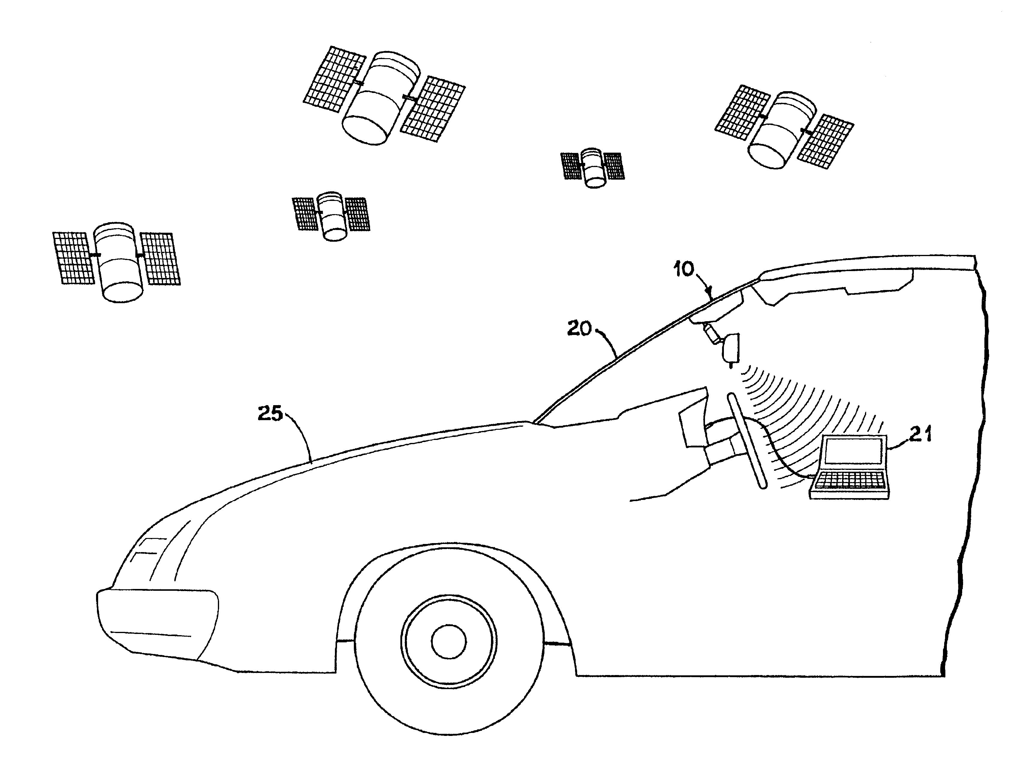
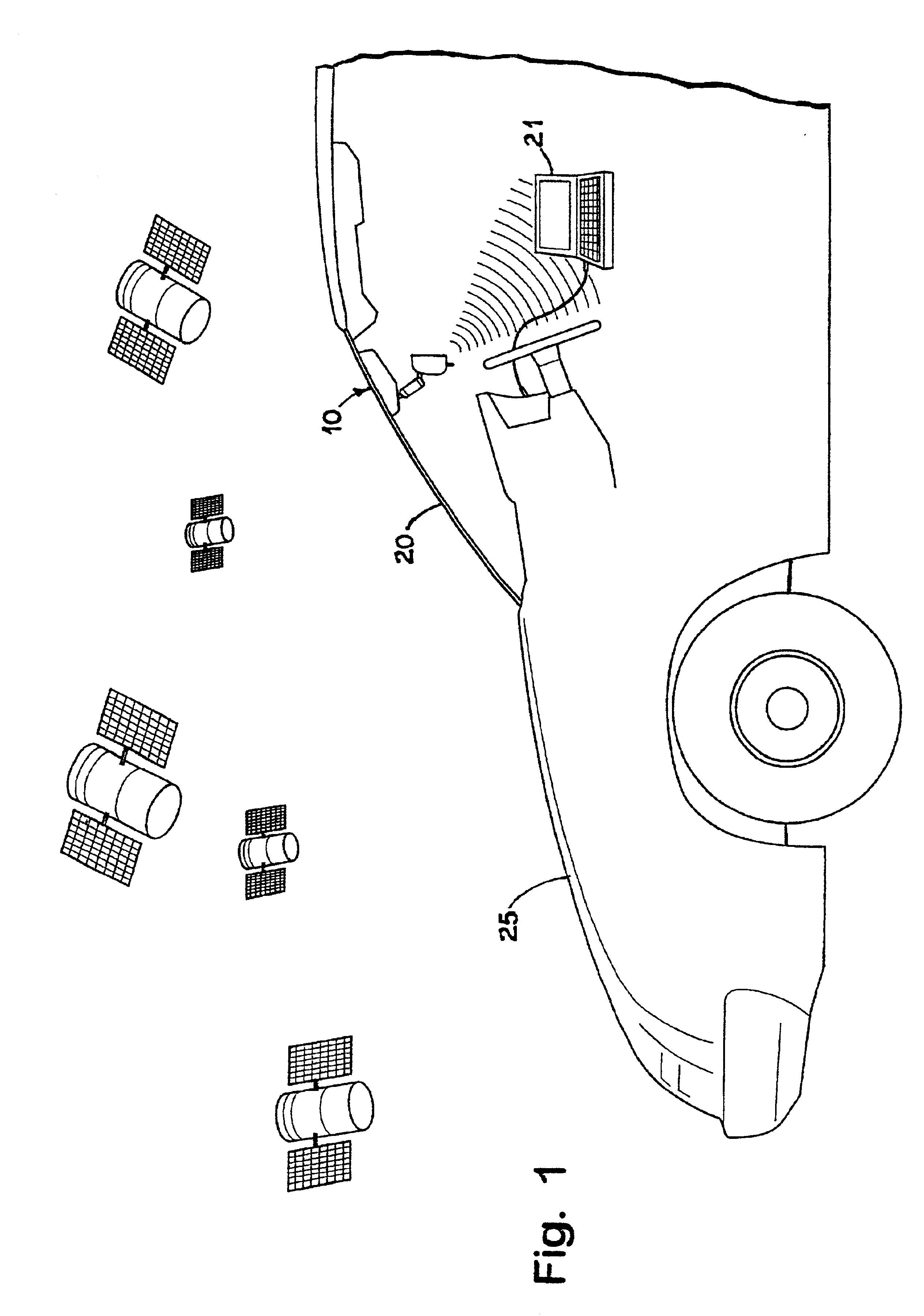
[0089]As noted above, the present invention pertains to a vehicle rearview assembly that incorporates some or all of the components of a vehicle communication and control system. As used herein, a “rearview assembly” is a structure that provides an image of a scene to the rear of driver. As commonly implemented, such rearview assemblies include an appropriately positioned mirror. A rearview assembly may additionally or alternatively include an electronic display that displays an image as sensed by a camera or other image sensor (see, for example, U.S. patent application Ser. No. 09 / 153,654 entitled SYSTEMS AND COMPONENTS FOR ENHANCING REAR VISION FROM A VEHICLE, filed on Sep. 15, 1998, by Frederick T. Bauer...


PUM


Abstract

A vehicle communication and control system is provided that may be more readily installed in a vehicle and that utilizes minimal additional wiring. According to some of the disclosed embodiments, the electrical components of the “brick” of a communication and control system are integrated into a rearview mirror assembly. Preferably, the microwave antenna for the GPS and the cellular telephone antenna are also integrated into the rearview mirror assembly. Various functions and features of the system are also disclosed.

Description

CROSS-REFERENCE TO RELATED APPLICATIONS[0001]This application claims priority under 35 U.S.C. §119(e) on U.S. Provisional Application No. 60 / 242,465 entitled VEHICLE REARVIEW MIRROR ASSEMBLY INCORPORATING A COMMUNICATION SYSTEM, filed on Oct. 23, 2000, by Robert R. Turnbull et al.; U.S. Provisional Application No. 60 / 216,297 entitled VEHICLE REARVIEW MIRROR ASSEMBLY INCORPORATING A COMMUNICATION SYSTEM, filed on Jul. 6, 2000, by Robert R. Turnbull et al.; and to U.S. Provisional Application No. 60 / 195,509 entitled VEHICLE REARVIEW MIRROR ASSEMBLY INCORPORATING A COMMUNICATION SYSTEM, filed on Apr. 6, 2000, by Robert R. Turnbull et al., the entire disclosures of which are incorporated herein by reference.[0002]This application is also related to commonly assigned U.S. patent application Ser. No. 09 / 444,176 entitled VEHICLE ACCESSORY MICROPHONE, filed on Nov. 19, 1999, by Robert R. Turnbull et al.; commonly assigned U.S. patent application Ser. No. 09 / 724,119 entitled VEHICLE ACCESSOR...

Claims


Application Information

Patent Timeline
IPC IPC(8): B60R1/12H01Q1/32H01Q5/00H01Q5/371H01Q9/04H01Q9/30H01Q21/28H01Q21/30H04B1/38H04B1/3805H04B1/3822H04M1/02H04M1/21H04M1/27H04M1/60H04R1/08
CPCB60R1/12H01Q5/371H01Q1/3266H01Q9/0407H01Q9/30H01Q21/28H01Q21/30H04B1/3805H04M1/6075H04M1/6091H04R1/08B60R2001/1223B60R2001/1261B60R2001/1284B60W2050/0081H04B1/3822H04M1/271H04M2250/02H04M2250/10H04R2499/13B60R1/1207B60W2050/0075B60W2556/60
Inventor TURNBULL, ROBERT R.KNAPP, ROBERT C.WALSTRA, ERIC J.WATSON, ALAN R.POE, G. BRUCEROBERTS, JOHN K.RUMSEY, WAYNE J.
Owner GENTEX CORP
Why Eureka
Try Eureka