Flowchart programming for industrial controllers, in particular motion controllers

a technology of motion controllers and flowcharts, applied in the field of flowchart programming for industrial controllers, can solve the problems of restricting user debugging options, affecting the user's understanding of the program, and the existing flowchart editors that do not provide adequate support for the creation of programs for both fields of applications, so as to improve the operating efficiency of the user, reduce or expand the form, and facilitate the user's understanding

Inactive Publication Date: 2005-12-27
SIEMENS AG
View PDF29 Cites 13 Cited by
  • Summary
  • Abstract
  • Description
  • Claims
  • Application Information

AI Technical Summary

Benefits of technology

[0029]In another advantageous embodiment of the present invention, the icons of the flowchart are automatically linked together. This also increases the operating efficiency of the user because the icons need not be linked together manually.
[0030]In another advantageous embodiment of the present invention, the flowchart may be shown in a reduced or enlarged form in the display. Due to this zoom function, the diagrams are easier to comprehend for the user, and furthermore, when the user is interested in certain program sequences, he can emphasize them graphicalally by enlarging them.
[0031]In another advantageous embodiment of the present invention, retranslation back into flowchart representation is possible because of markings in the textual language. Due to the use of syntactical and geometric information in the form of markings, it is possible to perform such reverse translation from the textual language into the flowchart view. The reverse translation option has the advantage for the user that changes entered at the level of the textual language can be implemented directly in the flowchart view through the flowchart editor and then become visible for the user in the flowchart diagrams. The user can then further process such retranslated programs with the help of the flowchart editor on the graphical level, and can subsequently generate control code from the said reconverted programs in the remaining procedure.
[0032]The main advantages achieved with this invention, thus, consist of the fact that icons for the flowchart editor, containing the function interface of the corresponding subprograms, are automatically generated from subprograms in textual language. If an original equipment manufacturer has already created subprograms in textual language, these subprograms can automatically expand the library of the flowchart editor with appropriate icons.
[0033]Another advantage is that a user can program both motion control functions and process control functions (programmable controller functions) in an appropriate form in a uniform programming environment. In addition, it is advantageous that the programming environment is project-sensitive, i.e., that additional dedicated language elements are made available to the user, depending on the underlying hardware or machine design.
[0034]Another advantage is that the user may use sequential as well as cyclic programming of control sequences. Since the user has access to interleaved module formation of function blocks he or she may simplify and improve the structure of his programs, because the design criteria, locality and high cohesion are easily implemented.

Problems solved by technology

The graphical input means and graphical editors available today for programming industrial controllers do not provide adequate support with regard to adaptive mechanisms for the hardware configuration on which an application is based.
Creation of programs for both fields of applications is not adequately supported by the existing flowchart editors.
Another disadvantage of the flowchart editors used today for programming industrial automation functions is that the diagrams created with these editors are either converted directly to executable processor code or to ASCII code, and must subsequently be interpreted in the respective target system through a run time-intensive process.
This system is not just inflexible with regard to porting and transfer of programs to other systems or machines, but does also restrict the user's debugging options.
Additional disadvantages of existing flowchart editors include the fact that only a limited, rigid and inflexible library of icons is available, and that the processing sequence of icons and the corresponding function blocks is predetermined.
Further, existing flowchart editors frequently offer only a limited number of possibilities for formulating synchronization mechanisms, although such mechanisms are frequently required, in particular for programming applications in industrial automation.

Method used


Image

  • Flowchart programming for industrial controllers, in particular motion controllers
  • Flowchart programming for industrial controllers, in particular motion controllers
  • Flowchart programming for industrial controllers, in particular motion controllers

Examples


Embodiment Construction

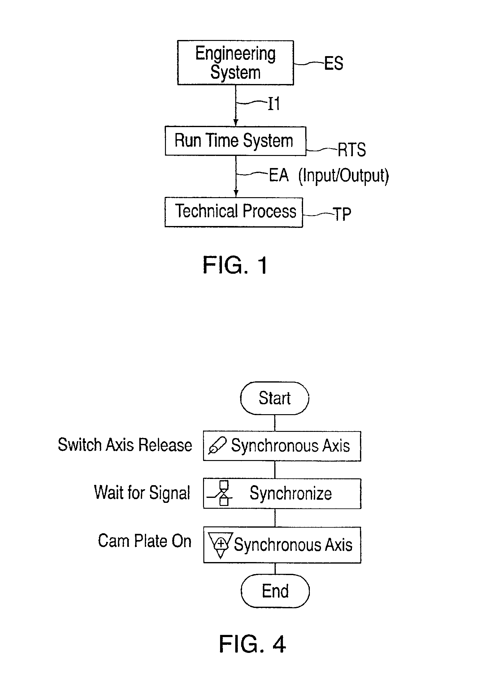
[0045]In FIG. 1, a block diagram shows that a technical process TP is controlled by the run time system RTS of an industrial controller. The connection between the run time system RTS and the controller, and the technical process TP, is bi-directional over the input / output EA. Programming of the controller and, thus, the specification of the behavior of the run time system RTS takes place in the engineering system ES. The engineering system ES contains tools for configuring, designing and programming machines, and for the control of technical processes. The programs generated in the engineering system are sent to the run time system RTS of the controller over information path I1. With regard to its hardware equipment, an engineering system ES usually comprises of a computer system with a graphical display screen (e.g., a video display unit), input means (e.g., a keyboard and mouse), a processor, working memory and secondary memory, a device for accommodating computer readable media ...


PUM


Abstract

A method for graphical programming of industrial controllers, in particular motion controllers, that automatically generates suitable graphical elements and respective masks in motion control flowchart notation from user-defined structured text subprograms of a structured textual language.

Description

FIELD OF THE INVENTION[0001]This invention relates to a method for programming industrial controllers, in particular motion controllers, where the user links graphical elements, in particular control structures and function blocks, with a graphical editor to form a flowchart that can be visualized on a display device.BACKGROUND[0002]In the industrial environment, it is known that graphical input aids and a display screen can be used for visualizing the control of the motion of a processing machine or a production machine (Hans D. Kief: NC / CNC Handbuch 2000 [NC / CNC Handbook 2000], Hansa Verlag, p. 254, FIG. 7 and p. 327, FIG. 6). The basic elements of graphical structure diagrams and flowcharts are defined in German Industrial Standard DIN 66,001.[0003]In addition, it is stated in the article “Visual Languages—an Inexorable Trend in Industry” (Josef Hübl, PLCs / IPCs / Drives—Convention Volume, pp. 88-95, Nov. 23-25, 1999, Nuremberg, Verlag, Hüthig GmbH, Heidelberg) that control flowchar...

Claims


Application Information

Patent Timeline
Patent Type & Authority Patents(United States)
IPC IPC(8): G05B19/05
CPCG05B19/056Y10S715/965
Inventor SCHMITT, REGINAWAGNER, PETER
Owner SIEMENS AG
Why Eureka
Try Eureka