
Apparatus for delivering carbonated liquid at a temperature near or below the freezing point of water

a technology of carbonated liquid and apparatus, which is applied in the direction of lighting and heating apparatus, couplings, domestic cooling apparatus, etc., can solve the problems of not being able to deliver beverages to the faucet, exceeding the cooling capacity of the machine, and saving energy costs, so as to slow down the ice turning process and reduce the likelihood of melting ice. , the effect of increasing the volume of beverages

Inactive Publication Date: 2006-01-03
MORGAN LOUIS A
View PDF15 Cites 44 Cited by
  • Summary
  • Abstract
  • Description
  • Claims
  • Application Information

AI Technical Summary

Benefits of technology

[0010]The present apparatus delivers the mixed soft drink beverage to the faucet at or below the freezing temperature of water which provides several benefits over the prior art. First, an advantage is gained by the beverage being less likely to melt the ice in a beverage glass upon dispensing the beverage, slowing the process of the ice turning to water which would dilute the beverage once dispensed. A second advantage is gained by the apparatus allowing for a greater volume of beverage being able to be dispensed at a lower temperature than the prior art devices because the inner tank of the double tank carbonator is not exposed to the environment surrounding the prior art carbonators, being insulated from the environment by either the vacuum in the void between the inner tank and outer tank or a highly insulating foam product. A third advantage lies in the cooling coils being contained within the same void as the inner tank, making the cooling coils transfer their cooling properties more efficiently to the inner tank and its contents than if the cooling coils were exposed to the environment of the prior art devices. This allows the refrigerant circulating system to run less often than the prior are systems, saving costs for energy required to operate the refrigerant circulating systems, which is the bulk of the cost of operation of these type of beverage dispensing units.
[0013]A secondary objective of the apparatus is to provide a more economically efficient method and space convenient component arrangement for pre-cooling the components being mixed into a carbonated beverage prior to their being combined and delivered to the faucet to enhance the efficiency of the beverage dispenser for lower the cost of operation. A third objective would be to provide the apparatus in a counter top embodiment for restaurant and concession use which is less effected by the surrounding environment of the location of the apparatus.

Problems solved by technology

The temperature of the dispensed beverage varies to a great extent, but no current machine is able to deliver the beverage to the faucet at or below freezing, the temperature of the beverage at the faucet being somewhere around 40 degrees.
In addition, only so much liquid may be chilled by the current machines before the liquid being dispensed starts being delivered at even higher temperatures, exceeding the cooling capacity of the machines.
Also significant in effecting these current machines in the environmental temperature surrounding the machines, outdoor dispensers being a greater challenge to regulate than indoor dispensers.
This allows the refrigerant circulating system to run less often than the prior are systems, saving costs for energy required to operate the refrigerant circulating systems, which is the bulk of the cost of operation of these type of beverage dispensing units.
However, with diet syrup, especially when flavored with the current artificial sweetener ingredients, these sweeteners are broken down when chilled too close to the freezing point of water, and can alter the flavorings to the point of making these artificial sweeteners become bitter.

Method used


Image

  • Apparatus for delivering carbonated liquid at a temperature near or below the freezing point of water
  • Apparatus for delivering carbonated liquid at a temperature near or below the freezing point of water
  • Apparatus for delivering carbonated liquid at a temperature near or below the freezing point of water

Examples


Embodiment Construction

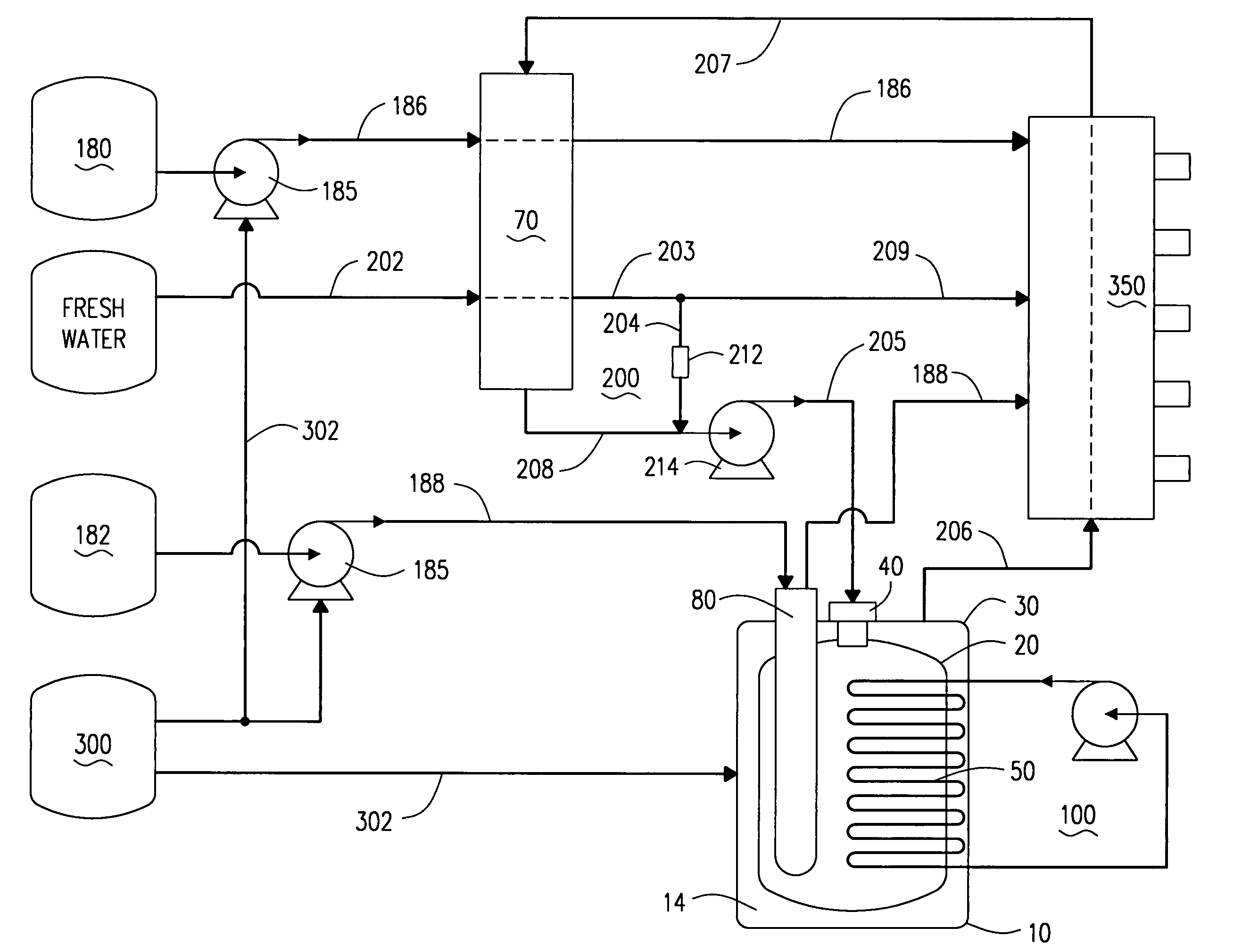
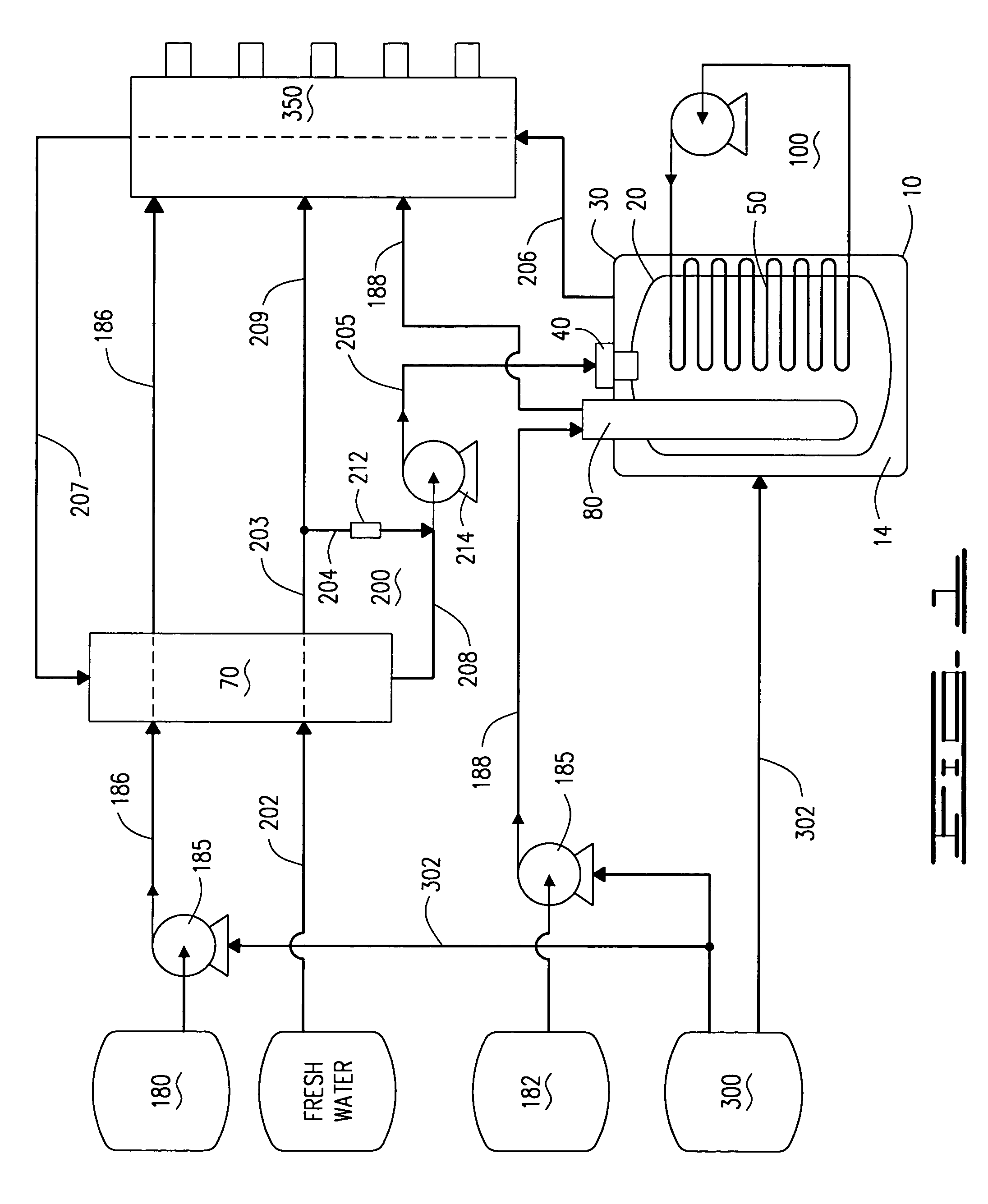
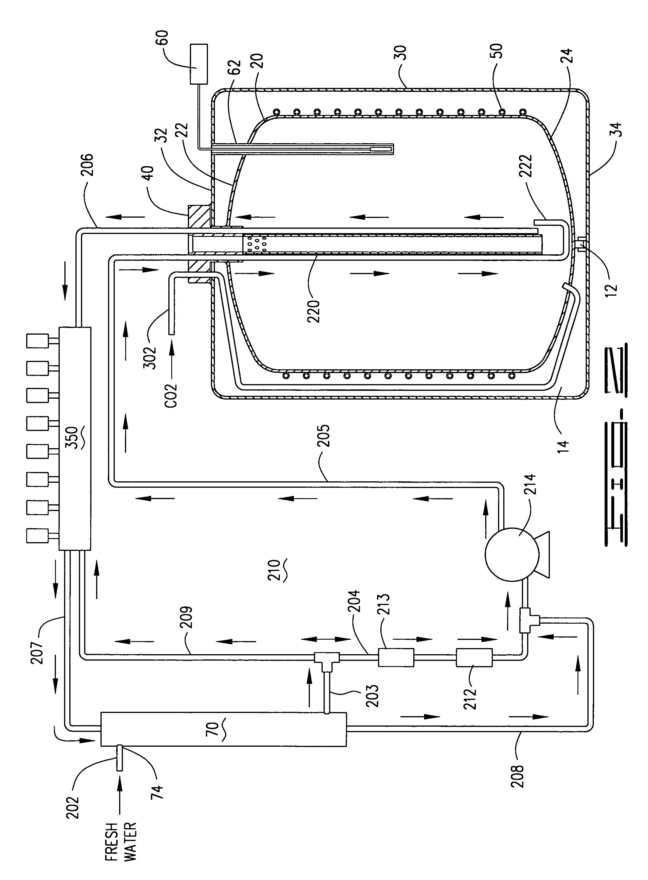
[0029]An apparatus for delivering a carbonated beverage at or near the freezing point of water, connected to a fresh water line, a carbon dioxide gas tank and a beverage syrup container which blends the fresh water, carbon dioxide gas and beverage syrup together for dispensing a cold soft drink is shown in FIGS. 1–13 of the drawings and comprises essentially a double tank carbonator 10, FIGS. 1–5, having an inner tank 20 and an outer tank 30, with an insulated void 14 between said inner tank 20 and outer tank 30, the inner tank 20 surrounded by a set of refrigerated cooling coils 50 integrated with a refrigerant circulating system 100, FIG. 3, a carbon dioxide cylinder 300 with compressed gas lines 302 directing carbon dioxide gas to the inner tank 20 and to a plurality of syrup pumps 185, a plurality of syrup lines 186, 188 connected to a plurality of syrup tanks 180, 182, including diet drink syrup tanks 180 and sugared syrup tanks 182, each syrup line 186, 188 connected to a sepa...


PUM

PropertyMeasurementUnit
Temperatureaaaaaaaaaa
Freezing pointaaaaaaaaaa

Abstract

A double tank refrigerated carbonated beverage dispensing apparatus for blending fresh water and carbon dioxide to produce a carbonated liquid delivered to a faucet bank for dispensing mixed soft drinks at a temperature at or below the freezing point of water, includes a double tank carbonator having in inner tank contained within an outer tank, insulated by a void between the two tank, the void having refrigeration coils connected to a refrigeration circulation system. The apparatus includes a soda water circulating system, a heat exchange unit for pre-cooling water and beverage syrup lines, syrup coils adapted to the double tank carbonator for chilling some beverage syrup lines, temperature sensors for regulating temperature of the carbonated water and fluid level probes to regulate the amount of water delivered to the double tank carbonator.

Description

CROSS REFERENCE TO RELATED APPLICATIONS[0001]Provisional Patent Application No. 60 / 428,333 filed Nov. 22, 2002.I. BACKGROUND OF THE INVENTION[0002]1. Field of Invention[0003]A double tank system and refrigerated compressor device for mixing water and carbon dioxide to produce a carbonated liquid within an inner tank, cooled by compressor coils attached to the inner tank, placed within the outer tank, with a vacuum or a highly insulated foam placed in a void between the inner tank and the outer tank, delivering the chilled carbonated water product to a faucet bank for mixing with a cooled beverage syrup, providing the carbonated beverage at a temperature at or below the freezing point of water, due to the enhanced cooling ability of the system and device.[0004]2. Description of Prior Art[0005]The following United States patents were discovered and are disclosed within this application for utility patent. All relate to a type of beverage dispenser having a compressor which delivers a ...

Claims


Application Information

Patent Timeline
IPC IPC(8): B67D5/62B67D5/56E03B1/00B67D7/80B67D7/74
CPCB01F3/04808B01F3/04815B01F5/106B01F15/065B67D1/0861B67D1/0014B67D1/0016B67D1/0057B67D1/0072B01F2015/061Y10T137/87153Y10T137/87571B01F23/2362B01F23/2363B01F25/53B01F2035/98B01F35/92
Inventor MORGAN, LOUIS A.
Owner MORGAN LOUIS A
Learn More