Method and apparatus for differential pressure testing of catalytic reactor tubes

a technology of catalytic reactor and differential pressure, which is applied in the direction of fluid pressure measurement, fluid tightness measurement, instruments, etc., can solve the problems of not providing any sort of electronic read-out or computer print-out that can be inspected and maintained as a record, and the overall integrity of the reactor servicing operation may be less than optimal, so as to achieve the effect of reducing the time and labor of servicing

Active Publication Date: 2006-01-03
WINDLASS METALWORKS
View PDF5 Cites 66 Cited by
  • Summary
  • Abstract
  • Description
  • Claims
  • Application Information

AI Technical Summary

Benefits of technology

[0015]It is another feature of the present invention to provide a novel method and apparatus for conducting blow-down of reactor tubes in a manner by-passing the usual back-pressure orifice and thus permitting a maximum allowable volume of air or other blow-down gas to be injected into the reactor tubes for removal of any dust that might be present therein.
[0016]It is also a feature of the present invention to provide a novel method and apparatus for conducting blow-down and/or back-pressure tests of groups of reactor tubes of a tube and shell type catalytic reactor and which has the capability of selectively electronically counting both in normal testing sequence and in inverted testing sequence to accommodate the movement direction and the orientation of the testing cart or carts relative to the upper tube sheet of the reactor and to accurately correlate the back-pressure tests of the reactor tubes with the numerical or other code tube identification system of the reactor so that the back-pressure test of each reactor tube is specifically identified and recorded.
[0017]It is also a feature of the present invention to provide a novel method and apparatus for accomplishing multiple tube testing of the reactor tubes of a catalytic reactor which permits identification and sequential recording of disabled reactor tube positions due to plugged tubes or the presence of thermocouple or other sensing devices in selected reactor tube openings of the uppe

Problems solved by technology

This single tube testing apparatus presents some test data in the form of a visual back pressure indication, but does not provide any sort of electronic read-out or computer print-out that can be inspected and maintai

Method used


Image

  • Method and apparatus for differential pressure testing of catalytic reactor tubes
  • Method and apparatus for differential pressure testing of catalytic reactor tubes
  • Method and apparatus for differential pressure testing of catalytic reactor tubes

Examples


Embodiment Construction

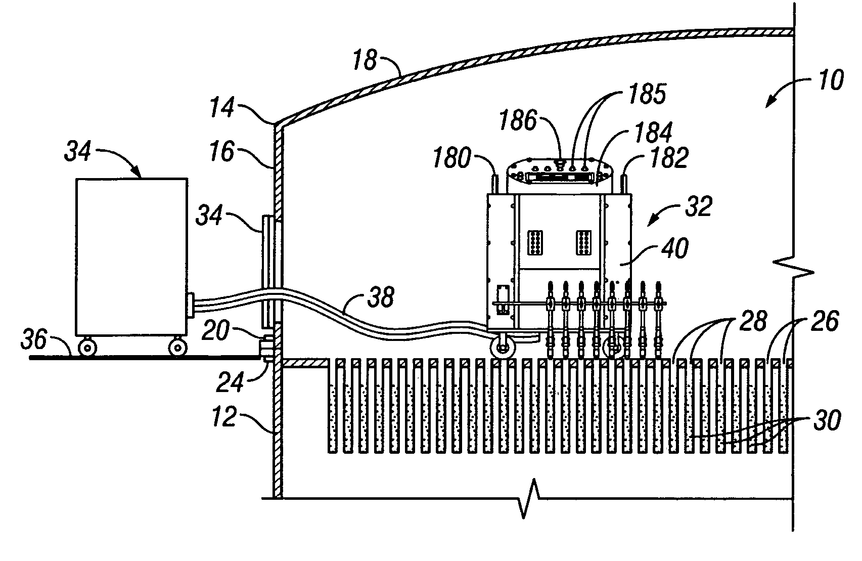
[0051]Referring now to the drawings and first to FIG. 1, a tube and shell type catalytic reactor is shown generally at 10 and incorporates a pressure containing reactor shell comprised of a reactor wall 12 that is typically of cylindrical configuration and a reactor dome 14 having a dome wall 16 and a curved upper dome wall 18. The reactor dome is provided with a mounting flange 20 which establishes sealing engagement with a support flange 22 of the reactor wall 12. Bolts or threaded studs and nuts 24 are employed to secure the flanges 20 and 22 in sealed assembly. Upper and lower tube sheets are mounted transversely of the reactor wall 12, the upper tube sheet 26 being shown in FIG. 1. The upper and lower tube sheets define a multiplicity of holes 28 within which the respective upper and lower ends of reactor tubes 30 are typically connected by welding. As mentioned above, a large tube and shell type catalytic reactor may have 20,000 to 80,000 reactor tubes, more or less, each cont...


PUM


Abstract

A multi-tube differential pressure (Delta P) testing system for testing catalyst filled tubes of tube and shell type catalytic reactors has at least one mobile test unit for movement on the upper tube sheet of a catalytic reactor. An array of test probes is mounted to the mobile test unit and is selectively positionable in sealed gas pressure communicating engagement within the upper ends of selected reactor tubes. A pressure testing gas delivery system is interconnected with the test probes and selectively communicates pressurized gas to the testing tubes at a blow-down pressure or selected test pressure determined by restricted orifices. A differential pressure measurement system measures the back-pressure resulting from application of test pressure to individual reactor tubes and having a computer receiving electronic back-pressure measurement data and producing an electronic and/or visual record correlated with a reactor tube numerical sequence and identifying the resulting back-pressure of each reactor tube of the multi-tube test. The testing system is capable of selectively electronically counting in normal sequence and in inverted sequence to accommodate test unit orientation and incorporates a separate manually positioned testing wand to accommodate tube positions of the reactor that cannot be readily accessed by one or more of the array of test probes.

Description

RELATED PATENT[0001]The subject matter hereof relates to U.S. Pat. No. 6,694,902 of Mathis P. Comardo, entitled “Delta P Testing System for Tube and Shell Type Catalytic Reactors”, issued on Feb. 24, 2004.BACKGROUND OF THE INVENTION[0002]1. Field of the Invention[0003]The present invention relates generally to tube and shell type catalytic reactors having a large number of catalyst containing tubes which are supported in a reactor chamber by upper and lower tube support sheets and which contain catalyst pellets for accomplishing a catalytic reaction with a fluid flowing through the catalyst containing tubes. More particularly, the present invention concerns a testing system for measuring differential pressure of the catalyst containing reaction tubes by introducing pressure at a predetermined flow rate into selected tubes and by reading the back-pressure of the tubes through a transmitter. Even more particularly, the present invention concerns methods and apparatus for identifying a...

Claims


Application Information

Patent Timeline
IPC IPC(8): G01L7/00
CPCB01J8/06B01J19/002G01N3/12G01M3/2815G01M3/2846G01M3/3227B01J2208/0007B01J2219/00268
Inventor COMARDO, MATHIS P.
Owner WINDLASS METALWORKS
Why Eureka
Try Eureka