CT detector-module having radiation shielding for the processing circuitry

a technology of processing circuitry and detector modules, which is applied in the field of computerized tomography (ct) xray imaging, can solve the problems of ct detector modules that are crowded, become non-functional, and are in the immediate neighborhood of each of the ct-modules in the ct-scanner

Inactive Publication Date: 2006-01-03
PHILIPS MEDICAL SYST TECH
View PDF11 Cites 44 Cited by
  • Summary
  • Abstract
  • Description
  • Claims
  • Application Information

AI Technical Summary

Benefits of technology

[0014]An aspect of some embodiments of the present invention relates to providing a CT detector-module comprising electronic components for processing signals generated by the module's detectors mounted in close proximity to the detectors and having sufficient radiation shielding for protecting the electronic components.

Problems solved by technology

Electronic components used to process signals from the X-ray detectors in a detector module are generally sensitive to radiation and if exposed to X-rays at intensities measured by the detectors are quickly damaged to an extent that causes them to become non-functional.
However, space available in a CT-scanner for a CT detector-module is limited and the immediate neighborhood of each of the CT-modules in a CT-scanner is crowded.
As a result it does not appear feasible to provide required data transmission capacity using conventional cable for CT detector-modules comprising a number of X-ray detectors substantially larger than a number of X-ray detectors typically comprised in prior art CT detector-modules.
However, it may not have appeared feasible to locate processing electronics for a CT detector-module in close proximity to the module's X-ray detectors.
As a result, it may have appeared in prior art that insufficient space in the neighborhood of the X-ray detectors of a CT detector-module is available to install radiation shielding sufficient to protect radiation sensitive electronic components located in close proximity to the detectors.

Method used


Image

  • CT detector-module having radiation shielding for the processing circuitry
  • CT detector-module having radiation shielding for the processing circuitry
  • CT detector-module having radiation shielding for the processing circuitry

Examples


Embodiment Construction

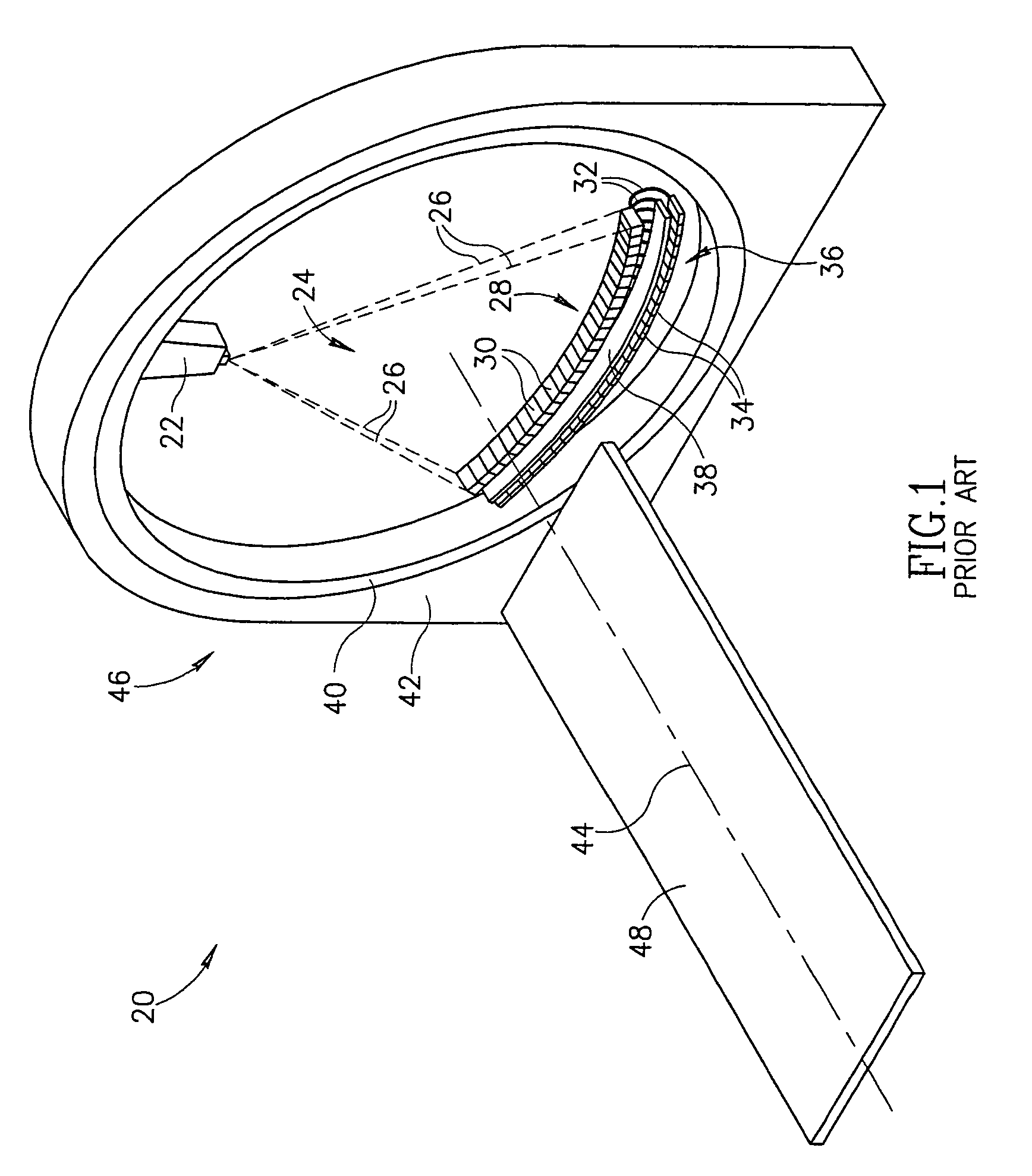
[0046]FIG. 1 schematically shows a third generation CT-scanner 20, in accordance with prior art. Only those features and components of CT-scanner 20 germane to the present discussion are shown in FIG. 1.

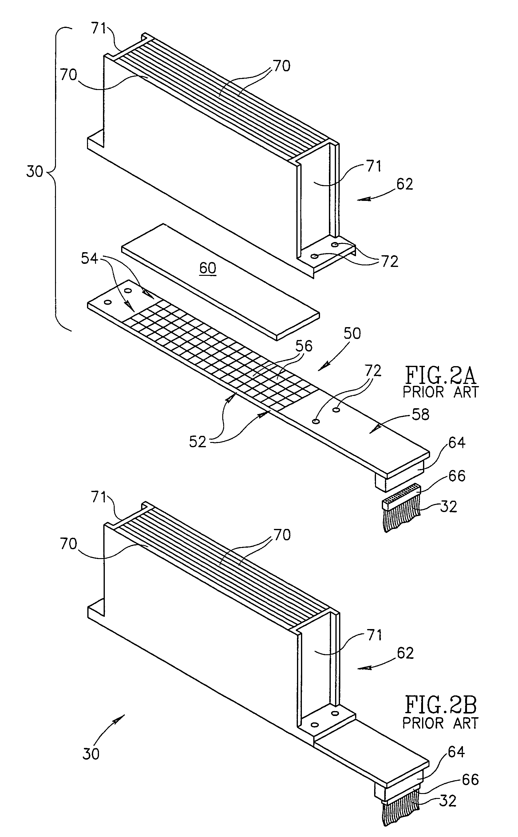
[0047]CT-scanner 20 comprises an X-ray source 22 controllable to provide an X-ray fan-beam 24, schematically indicated by dashed lines 26, and an array 28 of CT detector-modules 30 located opposite the X-ray source. Each CT detector-module 30 comprises a plurality of X-ray detectors (schematically shown in FIG. 2A but not shown in FIG. 1) for sensing intensity of X-rays in fan beam 24. Signals generated by the X-ray detectors in a detector module 30 responsive to X-rays incident on the detectors are transmitted via a cable 32 to a processing unit 34 that comprises electronic components (not shown) for processing the signals.

[0048]X-ray source 22 and CT detector-modules 30 are mounted to a rotor 40, which in turn is rotatably mounted to a stator 42 so that the rotor can be rotated abo...


PUM


Abstract

A CT detector-module-for detecting X-rays comprising: a matrix of photosensors, each of which generates signals responsive to photons incident thereon; a scintillator mounted over the matrix that converts X-rays incident on the scintillator to photons to which the photosensors are sensitive; an anti-scatter collimator mounted over the scintillator; and electronic circuitry located in close proximity to the photosensors to which each of the photosensors is connected for processing the signals generated by the photosensors; wherein parts of the module are formed from an absorbing material having a high X-ray absorption coefficient and shield the circuitry from radiation.

Description

RELATED APPLICATIONS[0001]The present application is a US National Phase Application of PCT Application No. PCT / IL01 / 01068, filed on Nov. 20, 2001.FIELD OF THE INVENTION[0002]The present invention relates to computerized tomography (CT) X-ray imaging, and in particular to methods of shielding electronics used to process signals generated by X-ray detectors in CT imagers.BACKGROUND OF THE INVENTION[0003]In CT X-ray imaging of a patient, X-rays are used to image internal structure and features of a region of the person's body. The imaging is performed by a CT-imaging system, hereinafter referred to as a “CT-scanner” that images internal structure and features of a plurality of contiguous relatively thin planar slices of the body region using X-rays.[0004]The CT-scanner generally comprises an X-ray source that provides a planar, fan-shaped X-ray beam and an array of closely spaced X-ray detectors that are substantially coplanar with the fan beam and face the X-ray source. The X-ray sou...

Claims


Application Information

Patent Timeline
Patent Type & Authority Patents(United States)
IPC IPC(8): G01T1/20A61B6/03G01T1/164G01T1/29G01T7/00H01L31/09
CPCG01T1/1648G01T1/2985G01T1/2018G01T1/2019G01T1/20182
Inventor ELGALI, AVNER
Owner PHILIPS MEDICAL SYST TECH
Why Eureka
Try Eureka