
Hand-held computers incorporating reduced area imaging devices

a technology of image sensor and reduced area, which is applied in the field of solid-state image sensor, can solve the problems of inability to process on-chip, huge power requirements of ccd device, and inability to meet the requirements of on-chip processing, so as to reduce the profile area, reduce the size and weight, and reduce the effect of area

Inactive Publication Date: 2006-01-03
CELLECT
View PDF59 Cites 110 Cited by
  • Summary
  • Abstract
  • Description
  • Claims
  • Application Information

AI Technical Summary

Benefits of technology

[0020]In all applications, to include use of the imaging device of this invention with a PDA, “camera on a chip” technology can be improved with respect to reducing its profile area, and incorporating such a reduced area imaging device within a PDA such that minimal size and weight is added to the PDA, and further that the imaging device can be used to image selected targets by the user.

Problems solved by technology

However, there are enormous drawbacks with CCD devices.
Two major drawbacks are that CCD devices have immense power requirements, and the amount of processing circuitry required for a CCD imager always requires the use of a remote processing circuitry module which can process the image signal produced by the CCD imager.
Also, because of the type of chip architecture used with CCD devices, on-chip processing is impossible.
Additionally, this hybrid is able to run on a low power source (5 volts) which is normally not possible on standard CCD imagers which require 10 to 30 volt power supplies.

Method used


Image

  • Hand-held computers incorporating reduced area imaging devices
  • Hand-held computers incorporating reduced area imaging devices
  • Hand-held computers incorporating reduced area imaging devices

Examples


first embodiment

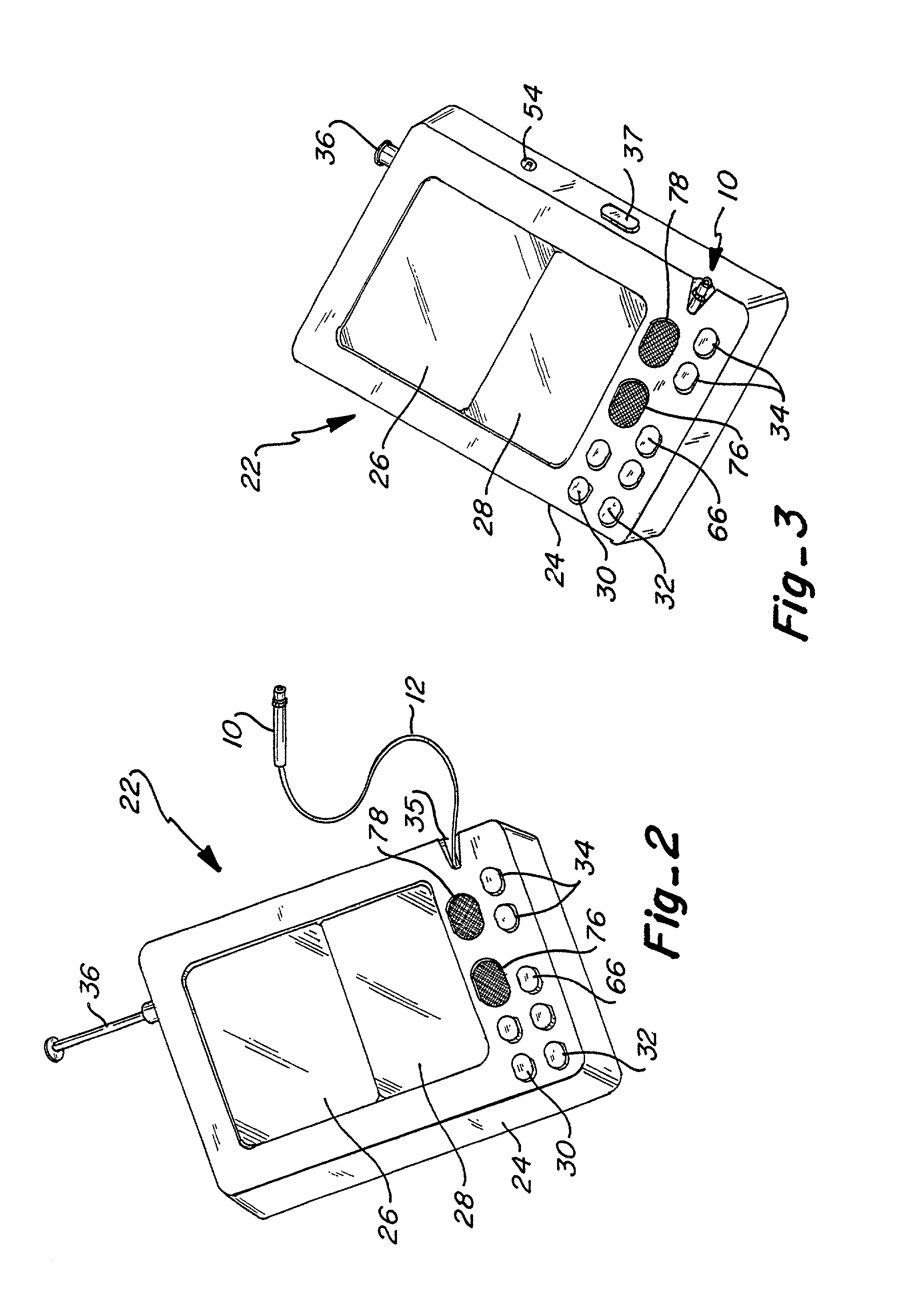
[0050]Now referring to FIGS. 2 and 3, a PDA 22 in a first embodiment is shown which incorporates the camera module 10. In basic terms, the PDA 22 is a miniature hand-held computer incorporating a video system enabling video to be taken by the camera module, and viewed on the video view screen 26, as well as enabling images to be stored and downloaded on a miniature computer disc (not shown) used with the PDA. Also discussed further below is the ability to transmit and receive audio and video signals.

[0051]Beginning first with a description of the basic components of the PDA 22, it includes a housing 24 which hold the components of the PDA and the video system. Cable 12 is housed within the housing 24 when in the retracted position. A spring biased spool (not shown) or some other known retracting device is mounted within the housing 24 enabling the cable 12 to be extended or retracted. A plurality of controls is provided enabling the user to manipulate the functions of the PDA. These...

second embodiment

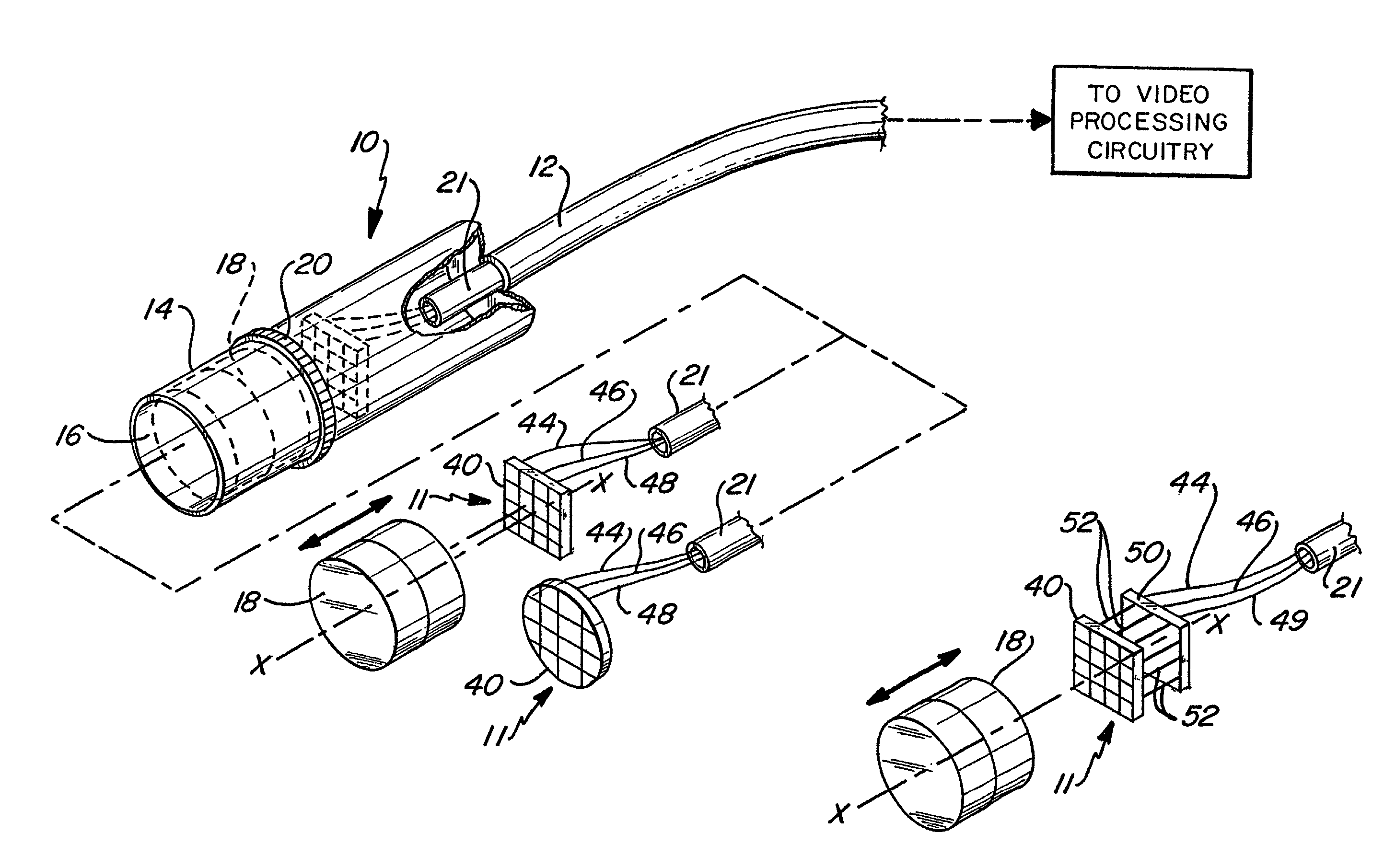
[0071]FIG. 9 is a schematic diagram illustrating one way in which the imaging device 11 may be constructed. As illustrated, the image sensor 40 may include the timing and control circuits on the same planar structure. Power is supplied to image sensor 40 by power supply board 64. The connection between image sensor 40 and board 64 may simply be a cable having two conductors therein, one for ground and another for transmitting the desired voltage. These are illustrated as conductors 44 and 46. The output from image sensor 40 in the form of the pre-video signal is input to video processor board 50 by means of the conductor 48. In the configuration of FIG. 7, conductor 48 may simply be a 50-ohm conductor. Power and ground also are supplied to video processing board 50 by conductors 44 and 46 from power supply board 52. The output signal from the video processor board 50 is in the form of the post-video signal and which may be carried by conductor 49 which can also be a 50 ohm conductor...


PUM


Abstract

A reduced area-imaging device is provided for use with a miniature hand-held computer referred to in the industry as a PDA. Various configurations of the imaging device are provided which position elements of the imaging device in desired locations. The PDA includes a miniature LCD-type video screen which can display not only images taken by the camera module, but also incoming video images. The camera module may communicate with the housing of the PDA either by a wired connection, or wirelessly. The camera module is small enough that it can be stored within the housing of the PDA. The camera module may be pointed at an object within sight of the user without having to move the PDA housing in order to take an image. Any acceptable wireless standard may be used for wireless communication between the camera module and the PDA. One particularly advantageous standard includes Bluetooth.

Description

[0001]This application is a continuation-in-part of U.S. Ser. No. 09 / 638,976 filed on Aug. 15, 2000 now U.S. Pat. No. 6,424,369, entitled “Hand Held Computers Incorporating Reduced Area Imaging Devices”, which is a continuation-in-part of U.S. Ser. No. 09 / 496,312, filed Feb. 1, 2000 now U.S. Pat. No. 6,275,255, and entitled “Reduced Area Imaging Devices”, which is a continuation application of U.S. Ser. No. 09 / 175,685, filed Oct. 20, 1998 now U.S. Pat. No. 6,043,839 and entitled “Reduced Area Imaging Devices”, now U.S. Pat. No. 6,043,839, which is a continuation-in-part of U.S. Ser. No. 08 / 944,322, filed Oct. 6, 1997 and entitled “Reduced Area Imaging Devices Incorporated Within Surgical Instruments”, now U.S. Pat. No. 5,929,901.TECHNICAL FIELD[0002]This invention relates to solid state image sensors and associated electronics, and more particularly, to solid state image sensors which are configured to be of a minimum size and used within miniature computer systems known as palm top...

Claims


Application Information

Patent Timeline
Patent Type & Authority Patents(United States)
IPC IPC(8): H04Q7/32A61B1/005A61B1/05G06F1/16G06F3/00H01L25/16H04N5/225H04N5/232H04N7/14
CPCA61B1/00016A61B1/00034A61B1/00048A61B1/00135A61B1/05G06F1/1616G06F1/1626G06F1/1671G06F1/1686G06F1/1698G06F3/005H01L25/167H04N5/2252H04N5/23203H04N7/142H01L2924/0002A61B1/0051G06F2200/1634H01L2924/3011H04N2005/2255H01L2924/00H04N23/555H04N23/51H04N23/66H04N25/76
Inventor ADAIRADAIR, JEFFREY L.ADAIR, RANDALL S.
Owner CELLECT
Learn More