

Suspending, guiding and propelling vehicles using magnetic forces
a technology of magnetic force and vehicle, applied in the field of suspension force, can solve the problems of low speed, high cost of magnet, no suspension force, etc., and achieve the effect of high operating speed and high acceleration
- Summary
- Abstract
- Description
- Claims
- Application Information
AI Technical Summary
Benefits of technology
Problems solved by technology
Method used
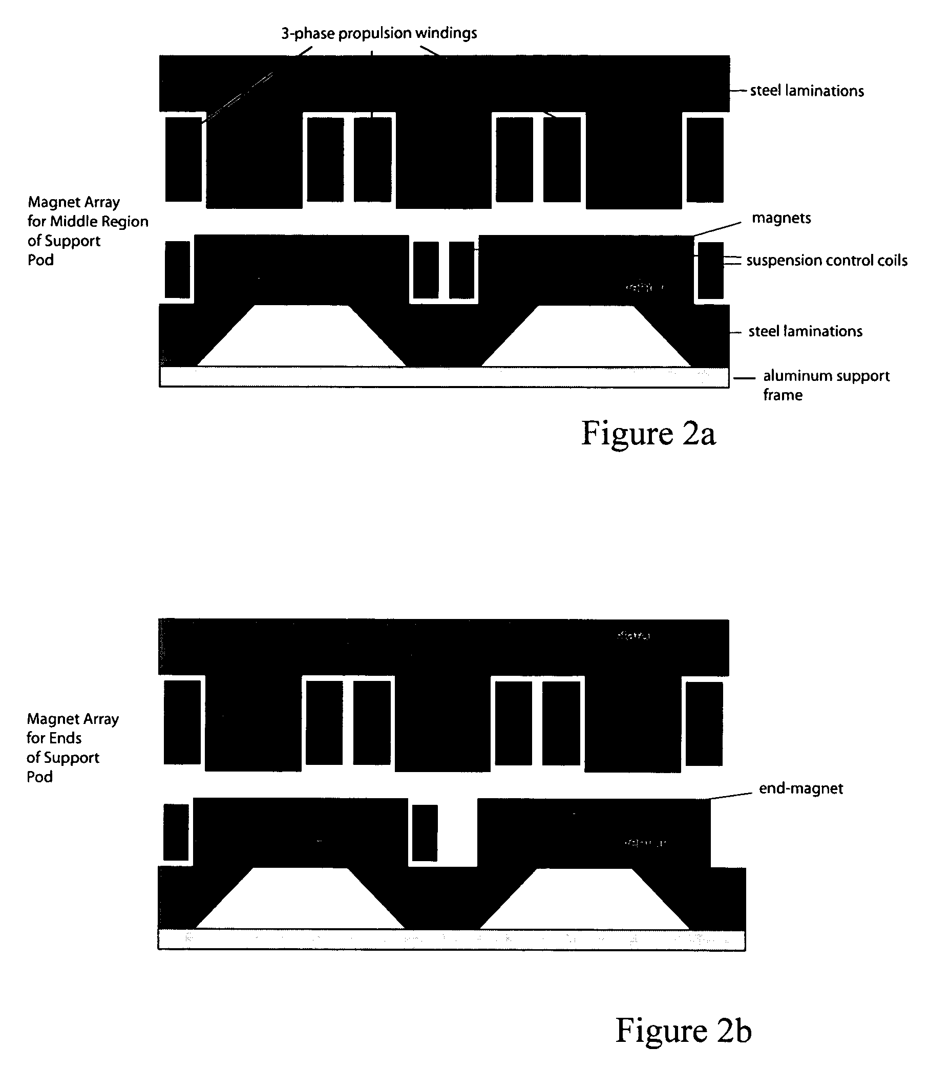
Image

Examples
Embodiment Construction
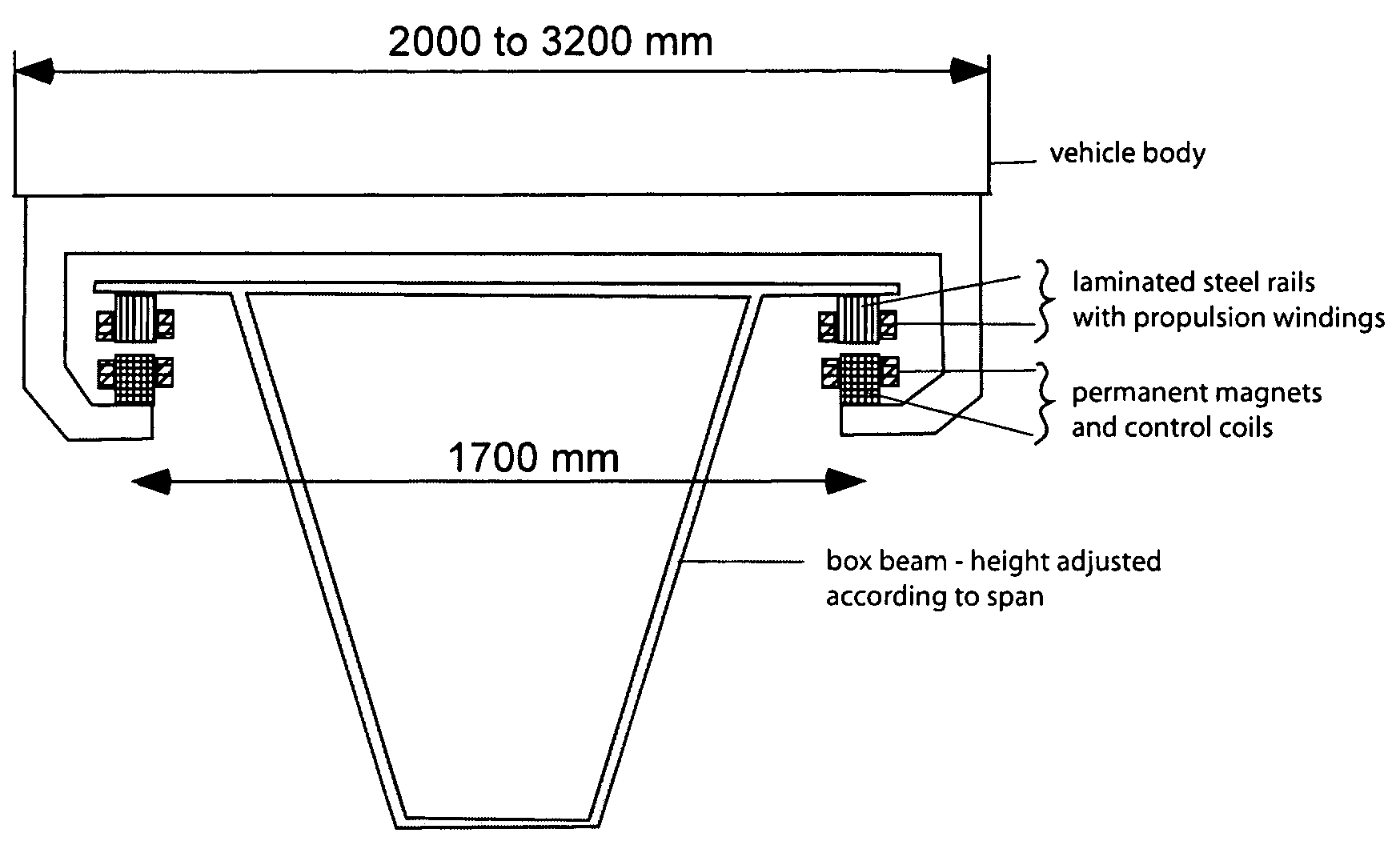
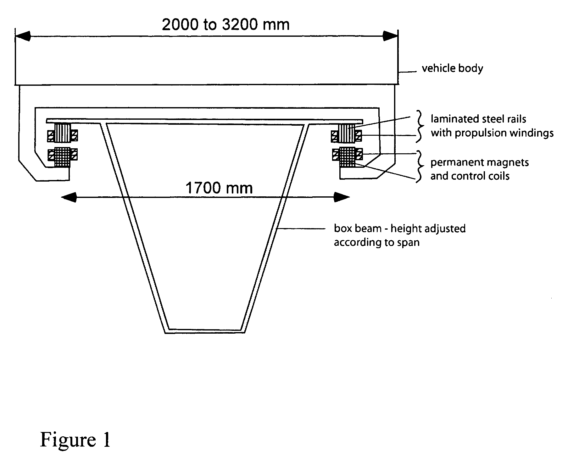
[0039]Systems according to the invention can use one magnetic structure to provide suspension, propulsion and guidance. In one embodiment, the suspension can lift about ten times the weight of the magnet structure and the integrated propulsion system can operate with an average efficiency of 90% or more. A transportation system using this suspension, propulsion and guidance can have lighter vehicles, consume less energy and still have the advantage of known maglev designs, e.g., reduced noise, higher top speed, higher acceleration and lack of maintenance associated with wheel-based systems.
[0040]Choice of Dimensions
[0041]FIG. 1 shows a cross-section of the baseline suspension design 10 in a system according to the invention. The vehicle 12 is supported by a string of magnets 18 on each side and these magnets create attractive forces to the laminated steel rails 14 on the guideway 24. Also shown is box beam 22. The dimensions shown in FIG. 1 were chosen with several factors in mind, ...
PUM
 Abstract
Description
Claims
Application Information