High density electronic cooling triangular shaped microchannel device

a microchannel device, triangular-shaped technology, applied in the direction of cooling/ventilation/heating modification, semiconductor device details, semiconductor/solid-state device details, etc., can solve the problem of low surface temperature and achieve the effect of high heat energy transport and low average surface temperatur

Inactive Publication Date: 2006-01-10
THE AEROSPACE CORPORATION
View PDF12 Cites 7 Cited by
  • Summary
  • Abstract
  • Description
  • Claims
  • Application Information

AI Technical Summary

Benefits of technology

[0007]An object of the invention is to provide a low average surface temperature thr

Problems solved by technology

The microchannels have a large heat conduction area that effectively sp

Method used


Image

  • High density electronic cooling triangular shaped microchannel device
  • High density electronic cooling triangular shaped microchannel device
  • High density electronic cooling triangular shaped microchannel device

Examples


Embodiment Construction

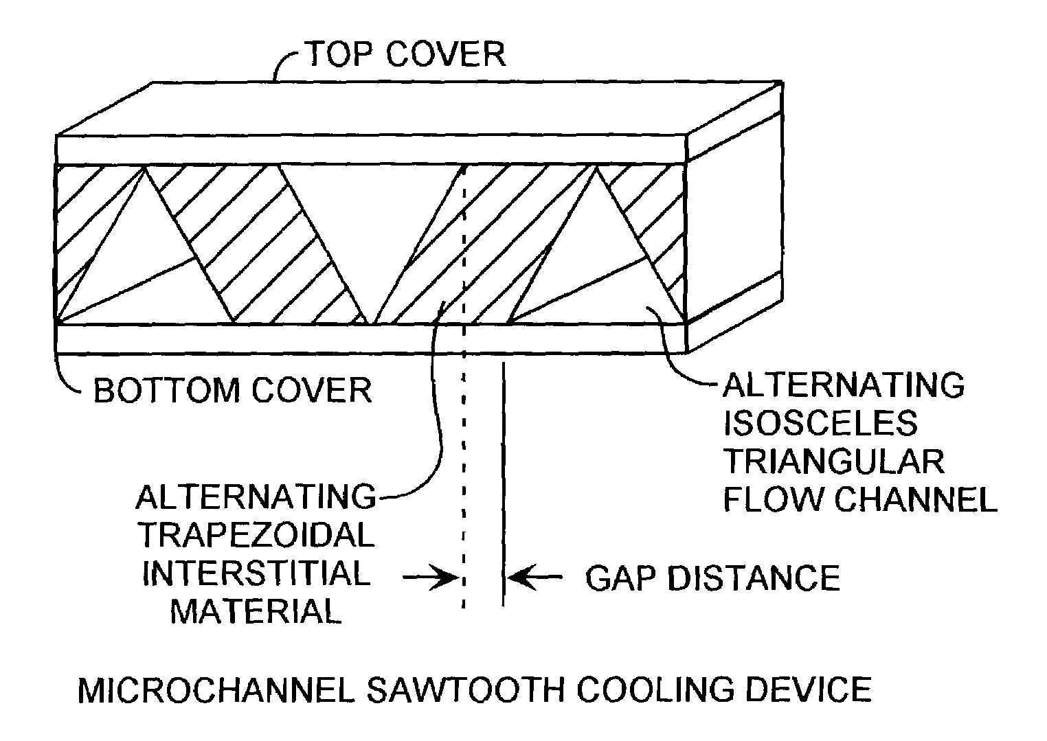
[0012]An embodiment of the invention is described with reference to the figures using reference designations as shown in the figures. Referring to FIG. 1, a microchannel sawtooth cooling device includes alternating isosceles triangular flow microchannels. Between the alternating triangular microchannels are formed alternating trapezoidal interstitial material. The microchannels and interstitial material are disposed between a top cover and a bottom cover. The top and bottom covers are preferably made of glass, but other covering materials may be used as well. Alternating upwardly and downwardly pointing microchannels are separated by a gap distance.

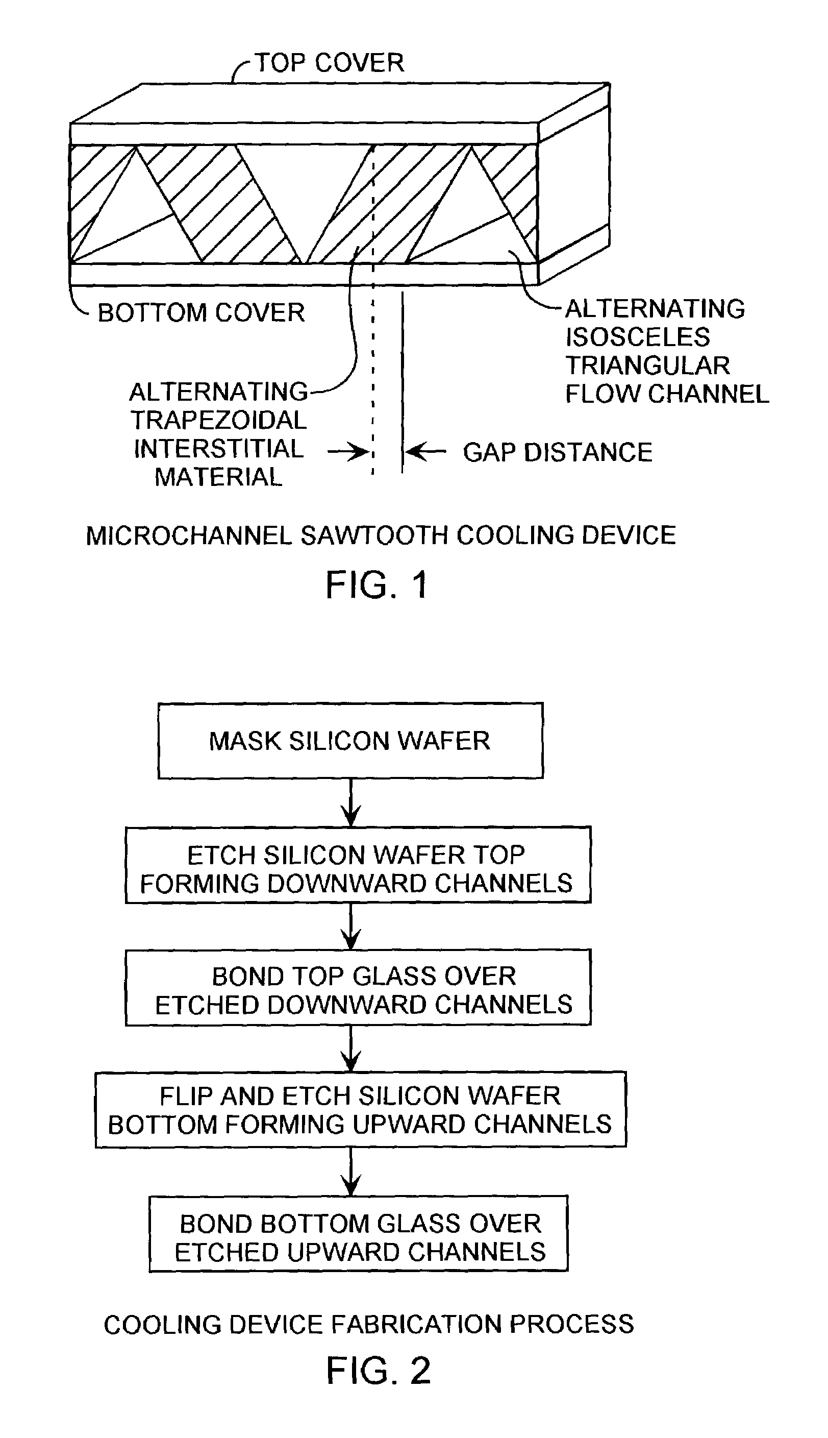
[0013]Referring to FIGS. 1 and 2, the triangular microchannels can be formed using conventional semiconductor processes and device fabrication process. The fabrication process may start with a silicon wafer that is firstly masked and then etched downward forming every other downwardly pointing triangular microchannel. The top cover glass ...


PUM


Abstract

An isosceles triangular cross section shaped microchannel-cooling device conducts a working fluid for the removal of heat from a heat source. The triangular shaped microchannel provides an increased thermal transport coefficient for improved heat transport with an improved mass flow rate. The microchannel-cooling device is well suited for removing heat from electronics, semiconductor components, and systems.

Description

FIELD OF THE INVENTION[0001]The invention relates to the field of electronics and semiconductor processing. More particularly, the present invention relates to the formation and use of fluid transport microchannels for cooling electronics and semiconductor components.BACKGROUND OF THE INVENTION[0002]The packing density of electronic components on chips continues to rise, thereby increasing the energy dissipation per unit surface area. In order to decrease the resulting high temperatures, fluid filled microchannel devices are used for thermal energy transport. Previous microchannels have had limited channel shapes or configuration of shapes to increase the heat removal capacity. Past investigations of microchannel with forced convective flows have used rectangular channel shapes. Normal heat removal rates are on the order of 3.4 W / cm2-° C. This low heat transfer rate forces electronic components to operate at high temperatures with reduced operational life.[0003]The capability of coo...

Claims


Application Information

Patent Timeline
IPC IPC(8): H05K7/20H01L23/473
CPCH01L23/473H01L2924/0002H01L2924/00
Inventor DICKEY, JAMES TODDLAM, TUNG TING
Owner THE AEROSPACE CORPORATION
Why Eureka
Try Eureka