Method of sorting dice by speed during die bond assembly and packaging to customer order

Active Publication Date: 2006-01-10
XILINX INC
5 Cites 19 Cited by

AI-Extracted Technical Summary

Problems solved by technology

Storage of finished goods in 20 differen...

Method used

[0031]In the prior art process of FIG. 1, there may have been a temptation not to package some of the dice, especially if only one or two dice of a given speed grade remain, and the process would require additional handling for these odd devices. However, in the process of the present invention, placing the unused dice in a storage location specific to the speed grade is easy to do, and keeping up with the inventory is also easy to do.
[0035]The process of the invention greatly simplifies inventory i...

Benefits of technology

[0016]Advantages of the structure and method are that packaged goods inventory can be greatly reduced or eliminated. Inventory is stored as unpackaged dice, giving flexibility for later choosing the package type when the goods are ordered. The dice can then be efficiently packaged to order. Also package marking of the speed grade can be done before final electrical test, which is an improvement in the packaging flow, and eliminates the need for re-marking packages for speed down-grade. The step of packaging to order can take a relatively short amount of time, and typically does not inconvenience the customer. Yet the manufacturer need not keep an inventory of finished g...

Abstract

When integrated circuit dice are tested as part of a completely manufactured wafer, the individual die is tested both for proper function and for speed grade. A wafer map is formed in a computer to keep up with which dice on the wafer are good and to record the speed grade of each good die. This wafer map is then used during the step of dicing and packaging the wafer to fill existing orders by placing a die that meets a speed grade of an order into the package that has been ordered. More than one kind of order can be filled from dice in a single wafer. The method allows integrated circuit devices to be packaged to order and eliminates the need to keep an inventory of packaged dice.

Application Domain

Technology Topic

Image

  • Method of sorting dice by speed during die bond assembly and packaging to customer order
  • Method of sorting dice by speed during die bond assembly and packaging to customer order
  • Method of sorting dice by speed during die bond assembly and packaging to customer order

Examples

  • Experimental program(1)

Example

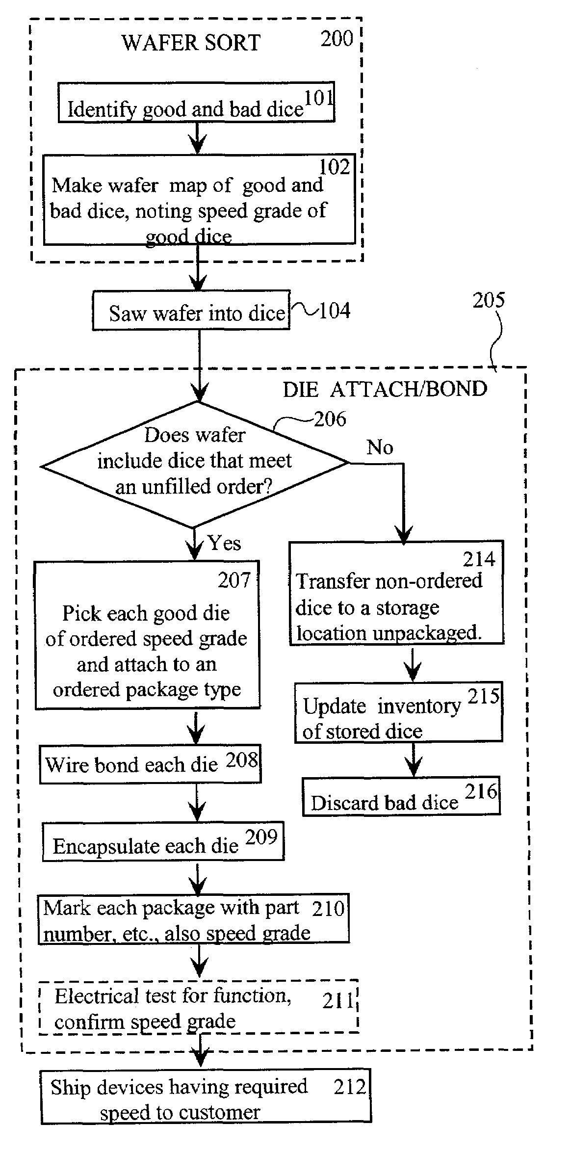
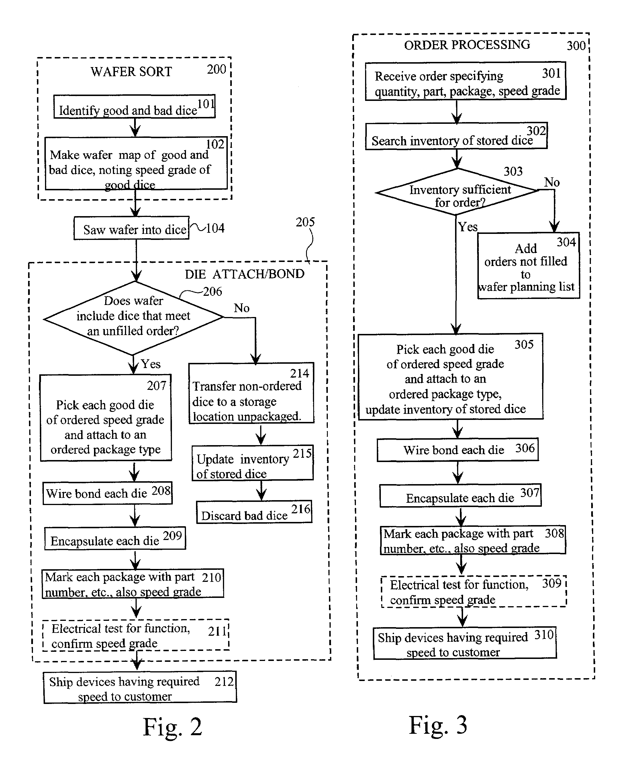
[0023]FIG. 2 shows a method according to the invention for processing a die from the completed wafer stage to being shipped to a customer.
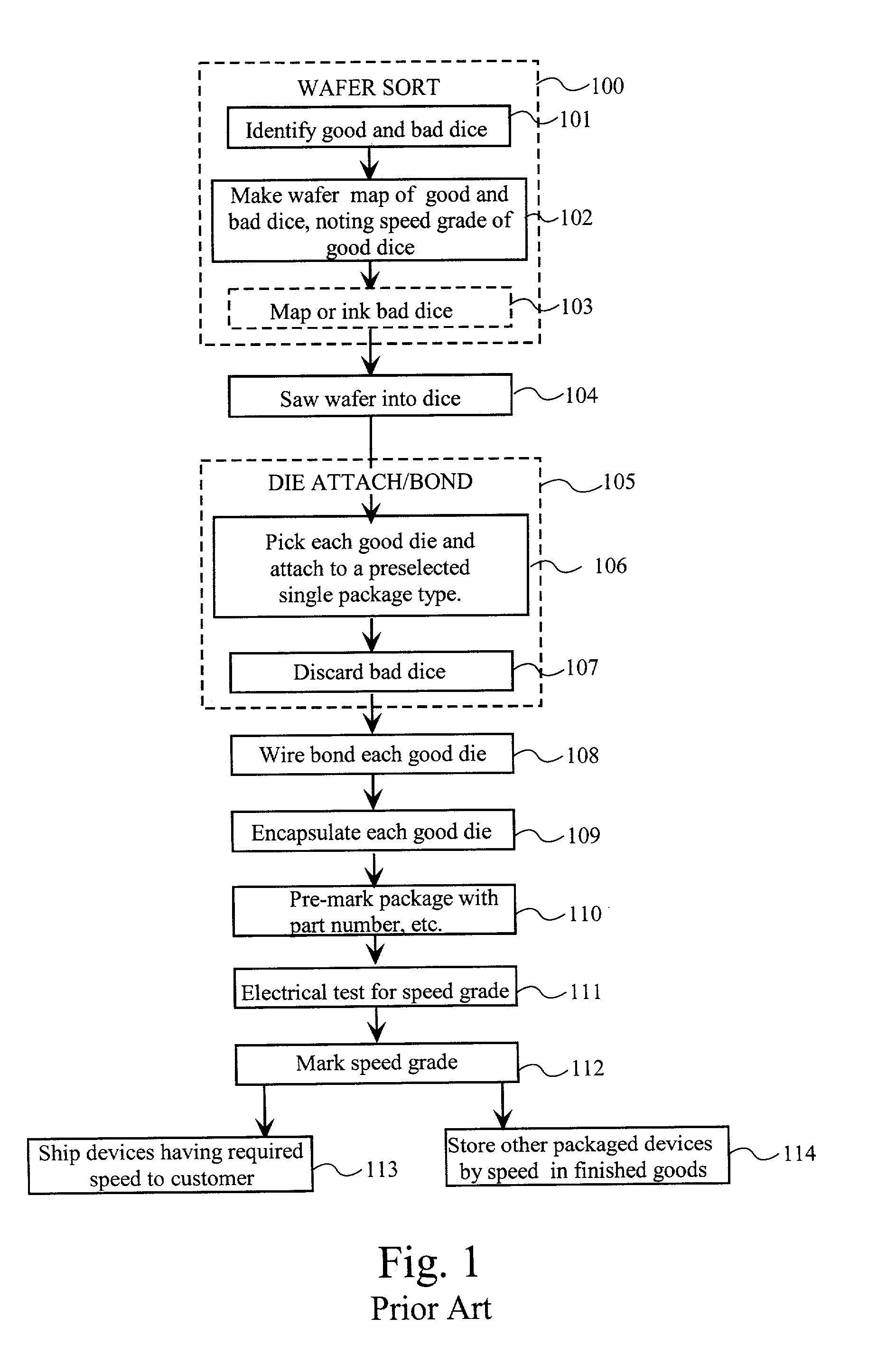
[0024]Wafer Sort process 200 begins as in the prior art with step 101 of identifying good and bad dice (chips). Next, at step 102, not only is a record made of how many good dice meet each speed grade, but a map of the wafer is made that indicates the speed grade of each good die on the wafer. This map is stored in a computer and is used later for processing after the wafer has been diced. As in the prior art, at step 104, the wafer is diced.
[0025]Then, according to the invention, die attach/bonding process 205 makes use of this wafer map. The die attach process takes into account what device types and packages have actually been ordered and participates in the process of filling the orders. At step 206, software associated with the die attach and bonding step determines whether the wafer includes dice that can fill outstanding orders. If so, at step 207, a programmed die attach machine responds to the customer order, sometimes several customer orders in parallel. For an order of devices at a first speed grade using a first package, the die attach machine picks dice of this first speed grade and places them into the first type of package until that order has been completed or until all dice of that first speed grade that are on the wafer have been placed into their packages. Then if there is a second order, the die attach machine places dice of a second speed grade into a second desired package until the order has been filled or until all dice of the second speed grade are placed. The die attach machine may complete more than one order of the same speed grade and same package type if such a combination of orders exists. This process may continue for third, fourth, etc. speed grades and package types until all ordered dice on the wafer have been matched with the order. Several orders of processing are contemplated with the invention. The die attach machine may proceed to fill a single order, completing as much of that order as possible before proceeding to another order. If the die attach equipment can handle several wafers simultaneously, a single order can be filled by picking from several wafers. As a further alternative, if many package types can be processed simultaneously, the die attach machine may proceed, using the wafer map as a guide, to fill as many orders as can be filled from a wafer.
[0026]At steps 208 and 209, as in the prior art process, each package-attached die is wire bonded to pins in the package and encapsulated.
[0027]Next, at step 210, the packaged dice are marked with relevant information including their speed grade, and in some cases, at step 211, a final electrical test is performed. At step 212, the packaged dice are shipped to the customer. If a customer's order is still incomplete after processing of a wafer or several available wafers, a particular shipment may be held until the next wafer is processed, or the order may be shipped in two batches.
[0028]While the processing of a single die occurs in the serial order shown, the equipment for carrying out the process is typically arranged in an assembly line, where as soon as a die has been attached to a package in step 207, the die attach machine will update the wafer map and again at step 206 question the order and the wafer map to determine whether the wafer still includes dice that meet an unfilled order. If there are more dice ordered, the die attach machine will pick the next die and attach it to a package.
[0029]Meanwhile, a die that has been attached to a package in step 207 will move to a wire bonding station where it will be bonded in step 208, encapsulated into a package at step 209, marked at step 210, possibly electrically tested at step 211, and shipped at step 212. Steps 208–212 are known steps when taken alone, and the novelty lies in the combination, particularly in being able to mark the packages at step 210 with a known speed grade and not having to re-mark later.
[0030]A preferred die attach machine will have the ability to place dice both into packages for shipment and into carriers or waffle packs for storage. If step 206 determines that good dice remaining in the diced wafer have not been ordered, at step 214, these good dice are transferred to a storage location such as a chip carrier where they are stored according to speed grade and at step 215 inventoried for later sale. Since these dice are not yet packaged, the stored inventory is more general purpose, since an un-packaged die can be placed into more than one package, as desired by a customer. At step 216, the bad dice are discarded.
[0031]In the prior art process of FIG. 1, there may have been a temptation not to package some of the dice, especially if only one or two dice of a given speed grade remain, and the process would require additional handling for these odd devices. However, in the process of the present invention, placing the unused dice in a storage location specific to the speed grade is easy to do, and keeping up with the inventory is also easy to do.
[0032]FIG. 3 shows steps for processing orders from an existing inventory of stored dice. A computer, for example, the same computer that keeps up with the wafer map, keeps up with remaining dice that have not yet been sold. When further orders are received at step 301, chip carriers or other storage devices are then available and can be moved into position so that dice can be picked from these carriers. At step 302, the computer searches its inventory of dice not sold for dice that satisfy the order. At step 303, the computer determines whether there is sufficient inventory to process the order. At step 304 the computer records any orders or parts of orders that can not be filled and this record is added to a wafer planning list. In one embodiment, the computer also manages wafer sorting in progress, as described in connection with FIG. 2, and if wafers in progress can help fill the order, the computer puts this information into the data base that controls the wafer sort and die attach process of FIG. 2. Thus, a single order may be filled partly from stored inventory and partly from wafers in process.
[0033]For filling a particular order, the computer must often choose between dice that have been stored and dice that are part of a wafer sorting process. In one embodiment, the computer gives preference to stored dice, thus rotating inventory on a somewhat first-in-first-out basis. In another embodiment, in order to reduce handling by eliminating the steps of moving dice to and from their storage locations, the computer gives preference to dice that are in the wafer sorting process.
[0034]Steps 305–310 are similar to steps 207–212. The difference is that at step 305, dice are picked from a storage device instead of from a wafer. Step 305 typically includes moving a storage container into position so that dice can be picked from the storage container. As discussed above, the steps typically occur in assembly line fashion with any particular die experiencing the processing steps serially as shown, but with several sequential processing steps being performed simultaneously. The inventory may be updated by an inventory control system operating in parallel with the computer that controls the die attach machine, or this computer may continuously update the inventory as the dice are picked.
[0035]The process of the invention greatly simplifies inventory in an industry which offers many different package types. Finished wafers are stored whole, or diced chips are stored unpackaged but identified. Sometimes a particular kind of device may be offered in as many as 20 packages. Storage of finished goods in 20 different kinds of packages is highly burdensome. The present invention can be used to completely eliminate the inventory of packaged goods (step 114 in FIG. 1) if all packaging is done to order. Thus the invention reduces the cost of manufacturing.
[0036]FIGS. 4 and 5 show records stored in the computer. FIG. 4 shows the record of wafers that have been tested and diced having chips not yet packaged or sold. The computer keeps up with the wafer number and stores information about good dice on the wafer, in particular their locations and speed grades. All dice on a wafer are the same type or part number, and another record not shown indicates the part number of each wafer. For a given wafer, for example wafer 36541 in FIG. 4, the location of each good die is stored along with its speed grade. In FIG. 4, for example the first line shows that there is a good die at location 31×12 (column 31 row 12) and that this die meets speed grade 5. Also shown in FIG. 4 is a record for wafer 36542 showing that 11 good dice remain and that they have speed grades from 6 to 8.
[0037]FIG. 5 shows three orders that have been placed for parts of type XCV1000. A customer has ordered 15 parts of speed grade 6 in package PQ240. The computer recognizes that this order can be filled from the two wafers illustrated in FIG. 3 because 15 of the dice on those two wafers are of speed grade 6. Thus those 15 dice will be packaged into PQ240 packages and shipped to the customer. If the customer had ordered a few more parts, some of the parts at speed grade 7 or 8 could have also been packaged and shipped to fill the order. Typically there will be more partly used wafers to choose from, not shown here, and it is preferable to fill an order of speed grade 6 with parts meeting speed grade 6 so that the faster parts can be saved for orders of faster parts.
[0038]From the above description, one of ordinary skill in the art can derive variations, and these variations are intended to fall within the scope of the present invention, which is defined by the claims.

PUM

no PUM

Description & Claims & Application Information

We can also present the details of the Description, Claims and Application information to help users get a comprehensive understanding of the technical details of the patent, such as background art, summary of invention, brief description of drawings, description of embodiments, and other original content. On the other hand, users can also determine the specific scope of protection of the technology through the list of claims; as well as understand the changes in the life cycle of the technology with the presentation of the patent timeline. Login to view more.

Similar technology patents

Classification and recommendation of technical efficacy words

Why Eureka
Try Eureka