Lamination stack with center interlock

Inactive Publication Date: 2006-01-10
L H CARBIDE
View PDF36 Cites 28 Cited by
  • Summary
  • Abstract
  • Description
  • Claims
  • Application Information

AI Technical Summary

Benefits of technology

[0022]One object of the present invention is to provide an improved method and apparatus for manufacturing and interlocking laminations.
[0023

Problems solved by technology

However, lamina material having a non-planar surface may interfere with the projection fully extending into the depression and thus reduce the amount of engaged surface area, unlike tabs which may extend and engage the

Method used


Image

  • Lamination stack with center interlock
  • Lamination stack with center interlock
  • Lamination stack with center interlock

Examples


Embodiment Construction

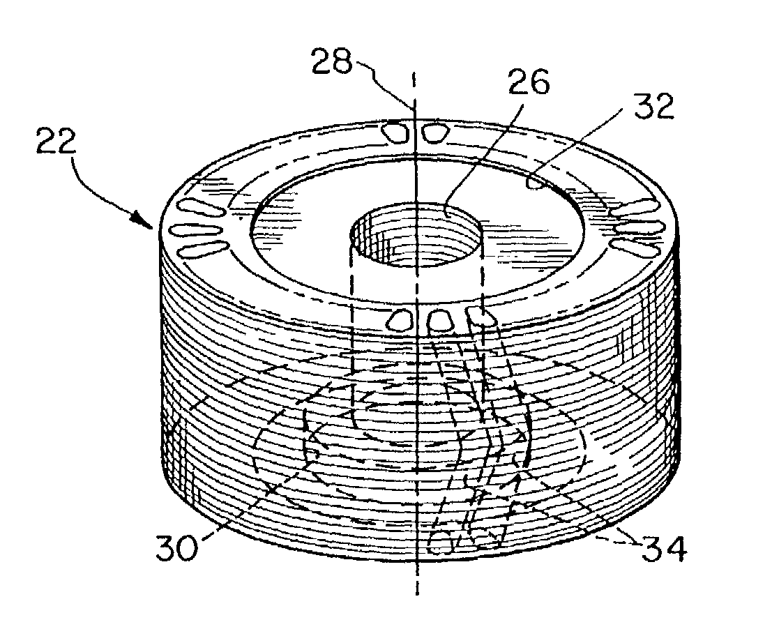
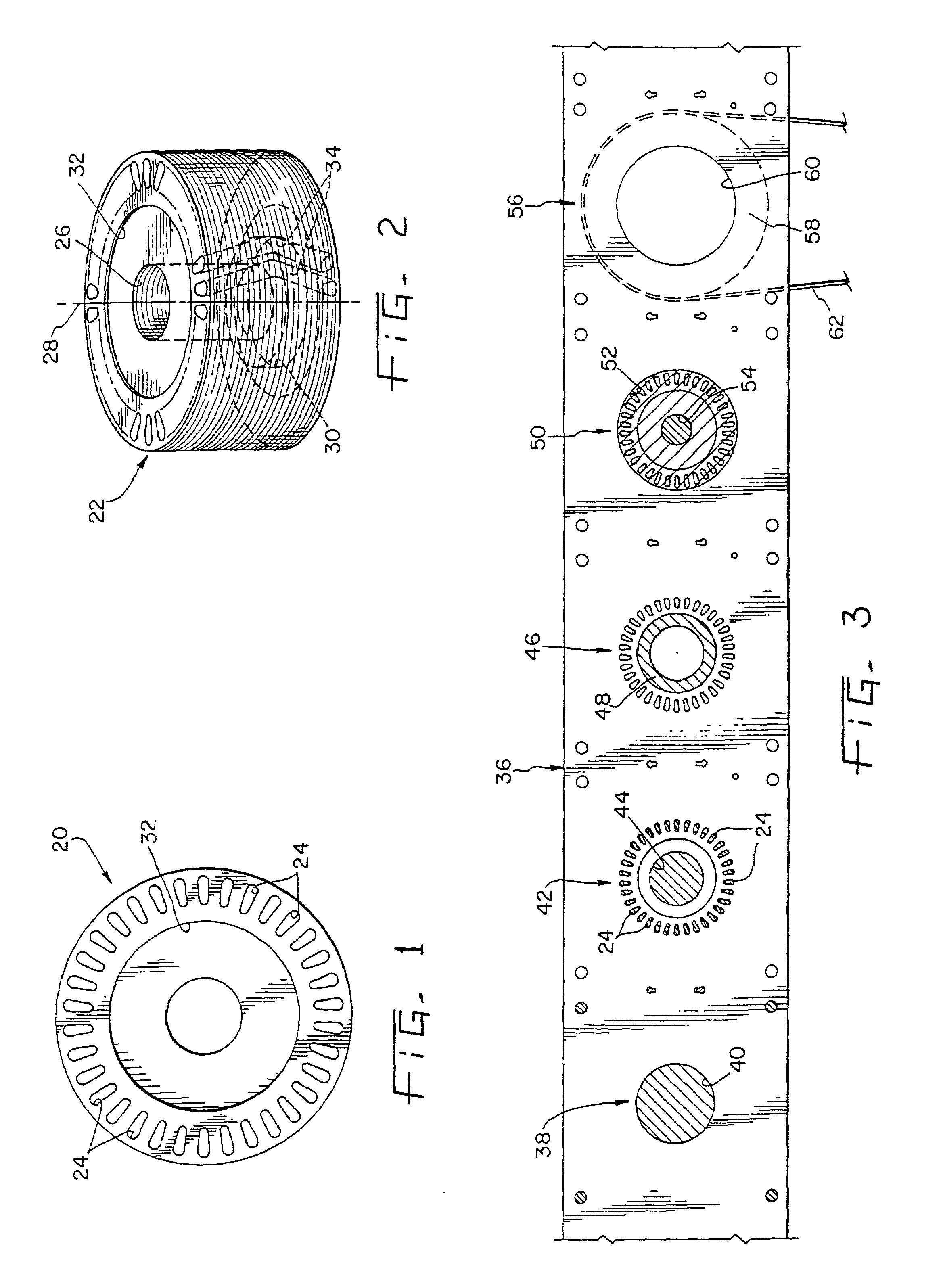
[0034]The present invention is a centrally interlocked lamination stack and the related method and apparatus for forming laminations to be used in making electromagnetic cores. Referring to FIG. 1, a single lamination (or lamina) is shown indicated by numeral 20 which when interlocked with additional laminations forms a stack which may be used to make laminated rotor core 22 of FIG. 2. For purposes of this application, the term “stack” shall refer to one or more laminations which are adapted to be aggregated and interlocked. Each lamina 20 has a plurality of teardrop shaped slot openings or conductor slots 24 spaced about and adjacent its perimeter, in this example thirty-four. Core 22 includes central shaft hole 26 having central stack axis 28, which includes counterbore 30 formed in the lower end of core 22. Each lamina excepting the bottom lamina in core 22 has centrally located indentation 32 with a central axis coaxial with central stack axis 28, indentation 32 forming a depres...


PUM

PropertyMeasurementUnit
Thicknessaaaaaaaaaa
Angleaaaaaaaaaa

Abstract

An interlocked stack of laminations for rotors wherein each lamination includes a centrally located, circular indentation. The indentation provides corresponding projections and depressions in the laminas which may be interlocked by engagement of a projection in one lamina with an adjacent depression in an adjacent lamina.

Description

CROSS REFERENCE TO RELATED APPLICATION[0001]This is a division of U.S. patent application Ser. No. 09 / 129,146, filed on Aug. 5, 1998, now U.S. Pat No. 6,237,214 which is a division of U.S. patent application Ser No. 07 / 966,876, filed on Oct. 26, 1992, now U.S. Pat. No. 5,809,638, issued on Sep. 22, 1998.BACKGROUND OF THE INVENTION[0002]1. Field of the Invention[0003]The present invention relates generally to techniques for forming laminations for magnetic cores such as the magnetic cores (rotors and stators) typically found in dynamoelectric machines. More particularly, the field of the invention is that of centrally interlocked lamination stacks used to manufacture magnetic cores and methods and machines (progressive dies) for processing the material (coil stock) which forms the laminations for such magnetic cores.[0004]2. Description of the Related Art[0005]Typically, the laminas are blanked from continuous strip stock and then stacked and bound together to form the rotor or stato...

Claims


Application Information

Patent Timeline
IPC IPC(8): H02K1/06B21D28/22H02K15/02
CPCB21D28/22H02K15/024H02K2201/09Y10T29/5317Y10T428/24322Y10T29/49078Y10T29/49009Y10T29/53143Y10T29/5138Y10T29/49012
Inventor NEUENSCHWANDER, THOMAS R.
Owner L H CARBIDE
Why Eureka
Try Eureka