High efficiency high speed low noise regulator

Active Publication Date: 2006-01-10
ANALOG DEVICES INC
View PDF3 Cites 69 Cited by
  • Summary
  • Abstract
  • Description
  • Claims
  • Application Information

AI Technical Summary

Benefits of technology

[0009]A novel voltage regulator is disclosed, which combines the positive attributes of both linear mode and switch mode regulators. The resulting re

Problems solved by technology

However, such regulators have a low efficiency when the voltage drop across the regulator is high, such as 0.5V to 5V, which happens often, especially when driving laser diodes.
Because of this, a linear mode regulator cannot provide a high average output current or power without generating a considerable amount of heat.
Although a rail-to-rail linear regulator can provide high output current without generating much heat in its saturation (or near saturation) region, the output current can no longer be regulated (or will soon be unregulated), and th

Method used


Image

  • High efficiency high speed low noise regulator
  • High efficiency high speed low noise regulator
  • High efficiency high speed low noise regulator

Examples


Embodiment Construction

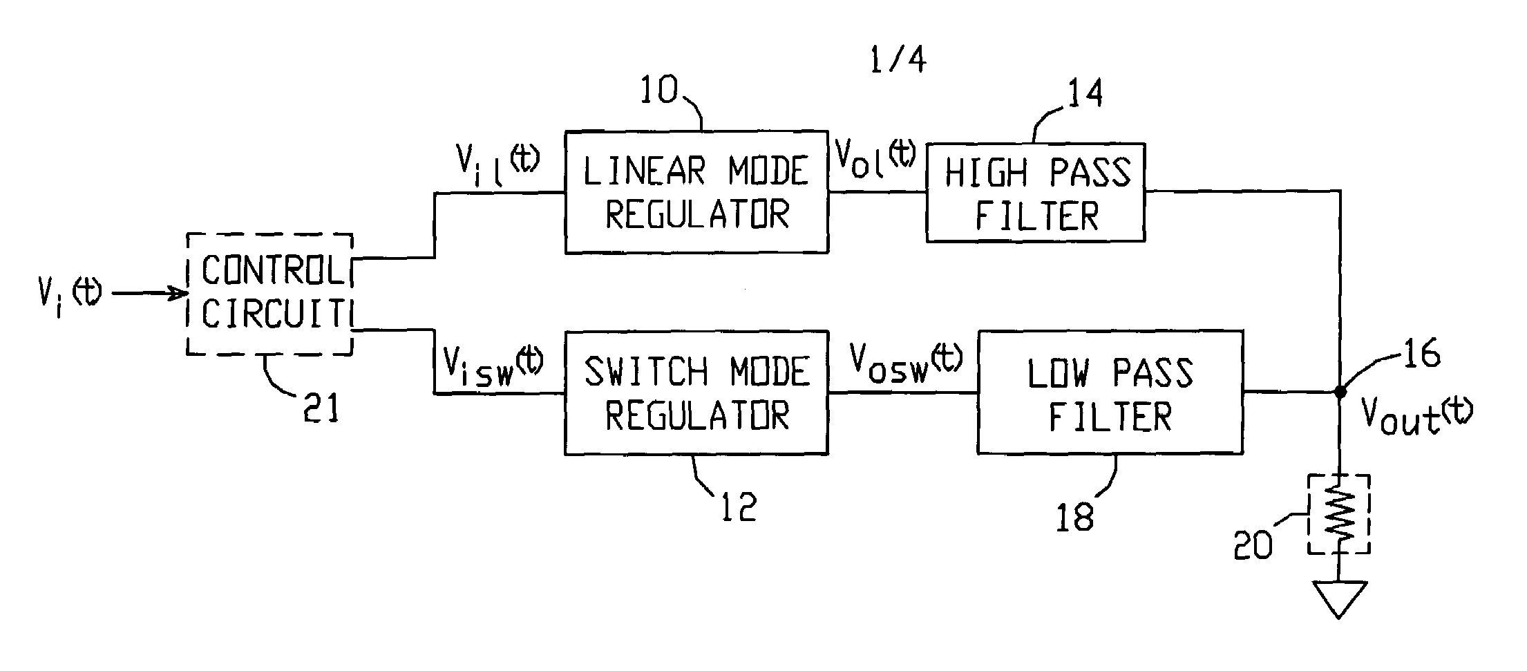
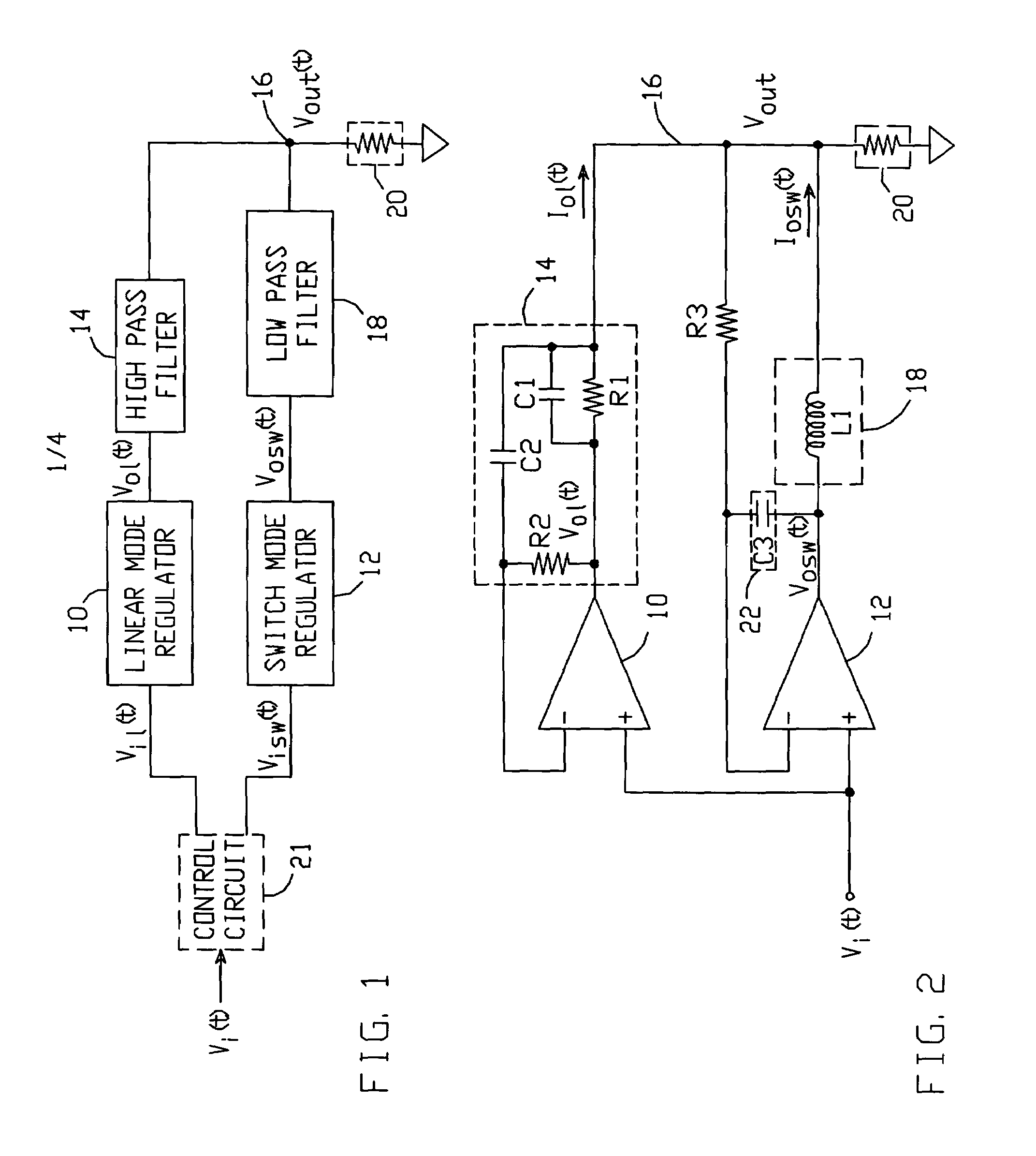
[0020]The basic principles of a voltage regulator in accordance with the present invention are illustrated in FIG. 1. The present regulator comprises a linear mode voltage regulator 10 and a switch mode voltage regulator 12. Linear mode regulator 10 produces an output voltage Vol(t) and switch mode regulator 12 produces an output voltage Vosw(t), in response to an input signal Vi(t) applied at the input side of a control circuit 21. A high pass filter circuit 14 is connected between output voltage Vol(t) and an output node 16, and a low pass filter circuit 18 is connected between output voltage Vosw(t) and output node 16. The voltage Vout(t) at output node 16 may be connected to drive a load 20. Input signal Vi(t) is provided by, for example, a signal source which operates the regulators as necessary to meet the needs of a particular load 20. Linear mode regulator 10 and switch mode regulator 12 may be activated with input voltages Vil(t) and Visw(t), respectively, provided by contr...


PUM


Abstract

A voltage regulator includes a linear mode regulator having a high pass filter circuit connected between its output and an output node, and a switch mode regulator having an low pass filter circuit connected between its output and the same output node. The high pass filter passes high frequency AC current provided by the linear mode regulator to the output node and reduces the low frequency AC and DC currents to substantially zero, and the low pass filter prevents the high frequency AC current produced by the linear mode regulator from being drawn by the switch mode regulator and passes the low AC and DC currents provided by the switch mode regulator to the output node. Thus, the present regulator offers the high response speed and low noise of a linear mode regulator, and the high power efficiency and large continuous output current capability of a switch mode regulator.

Description

[0001]This application claims the benefit of provisional patent application No. 60 / 456,610, to Liu et al., filed Mar. 20, 2003.BACKGROUND OF THE INVENTION[0002]1. Field of the Invention[0003]This invention relates to the field of voltage regulators, and particularly to high efficiency, high speed, low noise regulators suitable for powering diode lasers.[0004]2. Description of the Related Art[0005]One type of voltage regulator is an amplifier which receives an input voltage as a desired value and provides a regulated output voltage which follows the input voltage. A linear mode voltage regulator is a voltage regulator which works in linear mode; i.e., the output stage of the regulator has continuous current flowing between two transistor pairs. Linear mode regulators have the advantages of high precision, low noise, and fast response speed—i.e., a wide bandwidth from input to output.[0006]However, such regulators have a low efficiency when the voltage drop across the regulator is hig...

Claims


Application Information

Patent Timeline
IPC IPC(8): G05F1/40
CPCH02M3/158H02M2001/0045H02M1/0045
Inventor LIU, GANGBUXTON, JOSEPH C.COLLANTON, JR., PAUL R.
Owner ANALOG DEVICES INC
Why Eureka
Try Eureka