Fiber-optic compensation for dispersion, gain tilt, and band pump nonlinearity

a fiber optic and gain tilt technology, applied in the field of optical amplifiers, can solve the problems of loss, dispersion and gain equalization, inter-channel cross-talk, and difficult operation of wdm systems from around 1540–1560 nm, and achieve the effect of reducing the cost of operation, simplifying the system implementation, and minimizing the change of gain tilt across the currently used conventional band

Inactive Publication Date: 2006-01-10
NEPTUNE SUBSEA IP LTD +1
View PDF158 Cites 14 Cited by
  • Summary
  • Abstract
  • Description
  • Claims
  • Application Information

AI Technical Summary

Problems solved by technology

The limiting factors for a fiber-optic transmission line include loss, dispersion and gain equalization.
Another problem that arises in WDM systems is interaction or cross-talk between channels through nonlinearities in the fiber.
Consequently, if a fiber link is made from conventional DSF, it is difficult to operate a WDM system from around 1540–1560 nm.
For WDM systems using a number of bands, additional complexities arise due to interaction between and amplification in multi-band scenarios.
First, a new nonlinearity penalty arises from the gain tilt from the Raman effect between channels.
This arises because long wavelength channels tend to rob energy from the short wavelength channels.
In a WDM system with multi-bands, a complexity arises from interaction between the different pumps along the transmission line.

Method used


Image

  • Fiber-optic compensation for dispersion, gain tilt, and band pump nonlinearity
  • Fiber-optic compensation for dispersion, gain tilt, and band pump nonlinearity
  • Fiber-optic compensation for dispersion, gain tilt, and band pump nonlinearity

Examples


Embodiment Construction

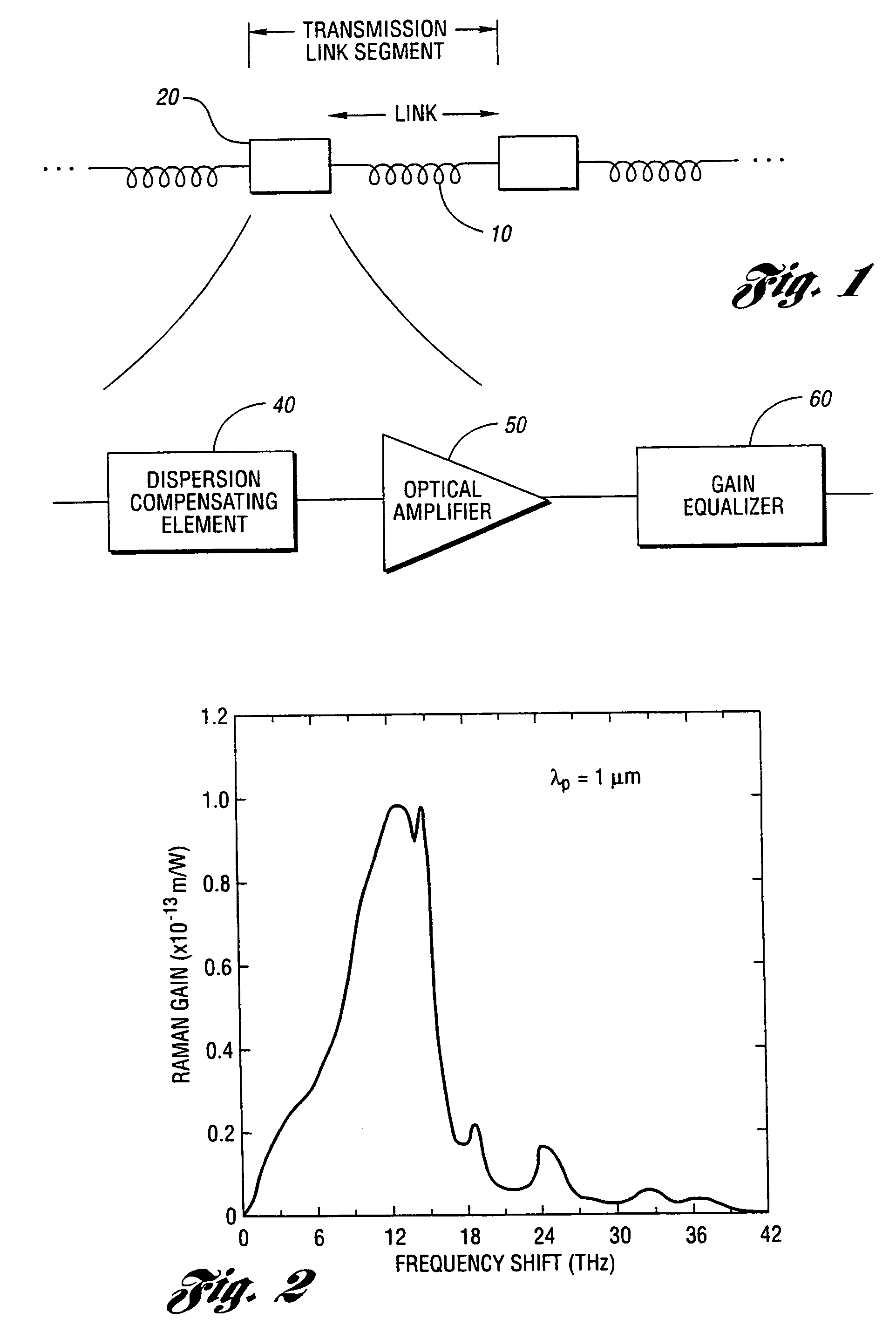
[0071]The present invention combines the functions of optical amplification and dispersion compensation advantageously to simplify the implementation of dispersion managed systems. The DMRA uses Raman amplification in a fiber that dispersion compensates for the surrounding transmission link.

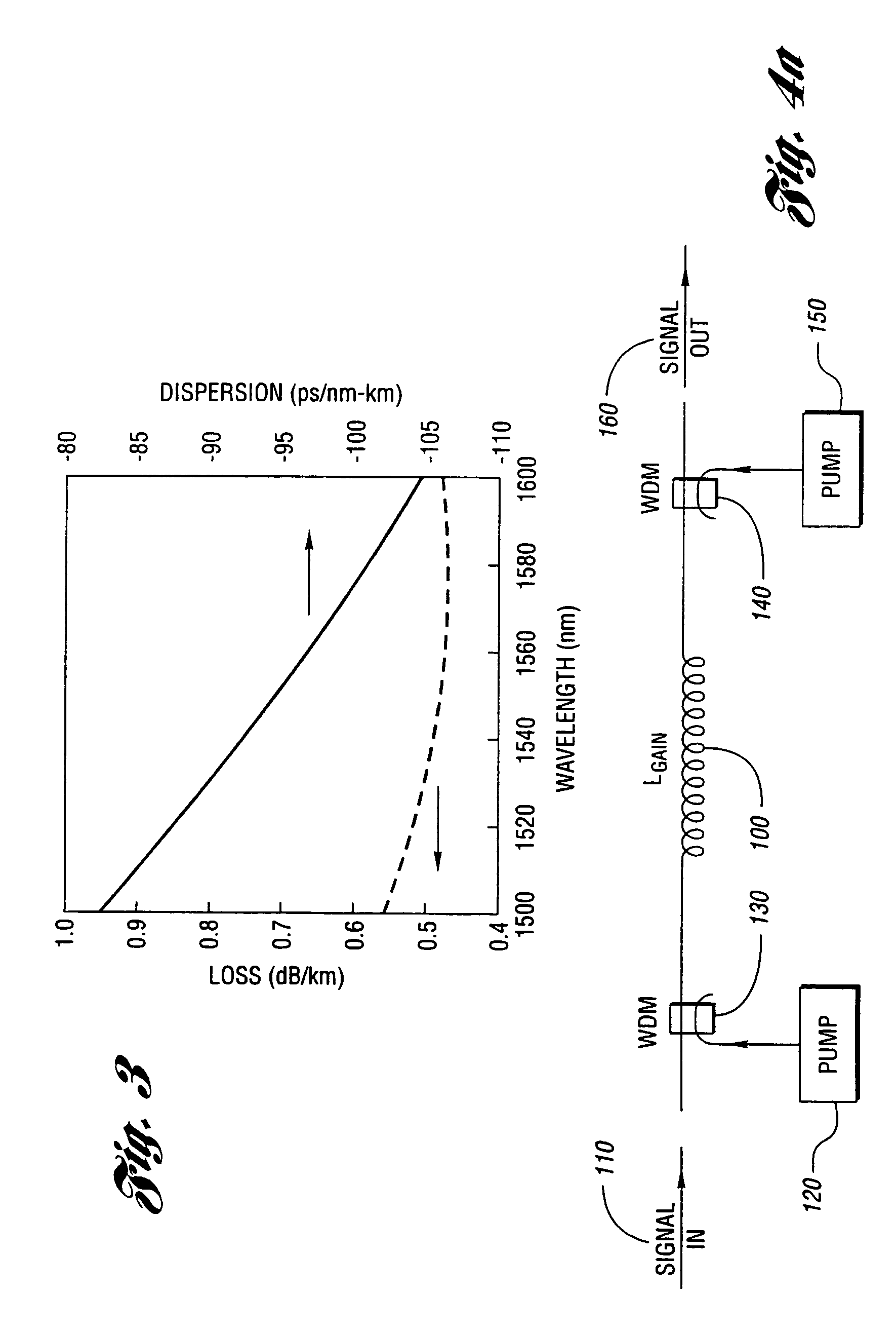
[0072]More specifically, the DMRA of the invention comprises an input port for inputting an optical signal having a wavelength λ, a distributed gain medium for receiving the optical signal and amplifying and spectrally broadening the same therein through Raman scattering, a pumping means operated at wavelength λp for generating a pumping light to pump the distributed gain medium, and an output port for outputting the amplified and spectrally broadened optical signal. The dispersion and length of the distributed gain medium is selected to be of the same magnitude of dispersion-length product as the transmission link but of the opposite sign of dispersion. The fiber is made single spatial mode for ...


PUM


Abstract

An apparatus and method are described for combining optical amplification and dispersion compensation in a Raman amplifier. A Dispersion-Managing Raman Amplifier (DMRA) combines Raman amplification with dispersion compensation by selecting the length and dispersion of the gain fiber to balance the dispersion of the link. This gain fiber is also single-mode at the signal and pump wavelengths. The pumping level is adjusted to balance the losses from the gain fiber and transmission link, while the pumping configuration is selected to remain within the 3 dB loss length for the pumping light. When the amplifier is split into two segments, the two segments may be joined by an isolator, a gain equalization element, and/or an optical add/drop multiplexer. For WDM transmission systems based on dispersion-shifted fiber (DSF), operation in the “violet band” between 1430–1530 nm is based on Raman amplification. By using a DMRA, a dispersion and nonlinearity managed system can be implemented. In particular, 4WM does not phase match in such a system, and modulation instability is absent in the transmission link. Furthermore, gain equalization can be added to the DMRA by cascading one or two Mach-Zehnder frequency filters. The invention also includes a method for symmetrically adding channels below and above the C-band, the gain tilt within the C-band can be minimized. Therefore, a roughly equal number of channels should be placed in the short-wavelength S-band and the long-wavelength L-band to minimize the Raman energy exchange in the C-band. Also, whereas C- and L-bands can be amplified using erbium-doped fiber amplifiers, the S-band can use either discrete or distributed Raman amplifiers. To minimize the interaction between pumps for different bands, alternate band pumps can be spatially dispersed and/or cross-polarized. The distributed Raman amplification can be achieved by pumping the transmission line with discrete laser diodes or by a Raman oscillator.

Description

[0001]This application claims the benefit of Provisional Application No. 60 / 089,426 filed Jun. 16, 1998.TECHNICAL FIELD[0002]The present invention relates generally to optical amplifiers used in fiber-optics for telecommunications, cable television and other fiber-optics applications. More particularly, the invention relates an optical amplifier that also provides dispersion compensation for a fiber-optic link as well as methods for minimizing gain tilt and apparatus for minimizing non-linear interaction between band pumps.BACKGROUND ART[0003]The demand for bandwidth continues to grow exponentially on fiber-optic superhighways due to applications such as data communications and the internet. Consequently, there is much effort at exploiting the bandwidth of optical fibers by using higher speeds per channel—so-called time-division multiplexed systems—and multiple wavelengths of light—so-called wavelength-division multiplexing (WDM).[0004]Most of the fiber-optic networks currently depl...

Claims


Application Information

Patent Timeline
Patent Type & Authority Patents(United States)
IPC IPC(8): H01S3/00H01S3/06H01S3/067H01S3/094H01S3/10H01S3/30H04B10/17H04B10/18
CPCH01S3/067H04B10/25253H04B10/2916H01S3/302H01S3/06758H01S3/094015H04B2210/003
Inventor ISLAM, MOHAMMED N.ISLAM, MOHAMMED A.SLAWSON, MICHAEL R.
Owner NEPTUNE SUBSEA IP LTD
Why Eureka
Try Eureka