
Implantable electrode lead

Inactive Publication Date: 2006-01-10
TERUMO KK
View PDF5 Cites 28 Cited by
  • Summary
  • Abstract
  • Description
  • Claims
  • Application Information

AI Technical Summary

Benefits of technology

[0011]The present inventors have made a detailed study on an implantable electrode lead to be used in conjunction with such an implanted device as a cardiac pacemaker and a defibrillator, to find that by imparting lubricity only to specific portions of a conducting part, the lead excels in the workability in the introduction thereof, also excels in the workability in the ligation thereof to a vital tissue via a suturing sleeve because an insulating coat in contact with an inner surface of the suturing sleeve is not provided with a lubricating coat layer, and thus the lead can be fixed on the vital tissue with high stability for a long time. This invention has been perfected based on this discovery.
[0013]According to this invention, by defining the range of the lubricating coat part to be applied to the surface of the conducting part, it is made possible to provide such an implantable electrode lead as to be designed so as to excel in the workability in the introduction and to secure the stable fixing by suturing.

Problems solved by technology

When these two leads are to be introduced into a small blood vessel or a tortuous blood vessel, they possibly interfere with each other to an extent of rendering the introduction difficult and they have even a possibility that the formerly implanted lead will be moved out of position by the subsequently implanted lead.
When the lubricity of the surface of the conducting part is improved by coating the surface with a hydrophilic polymer as described in JP-A-08-10338, however, although the introduction of the lead during the implantation process can be easily attained, the subsequent ligation of the lead to a vital tissue by means of a suturing sleeve entails a possibility that the suturing sleeve would slip on the conducting part to degrade the fastness of the ligation and thus the lead could not stably fixed in a body.
As a result, there is also a possibility that the electrode would be randomly moved or even slipped out to render the pacing and the sensing imperfect.
This adverse effect results in harming the performance which the implanted device such as a cardiac pacemaker or a defibrillator ought to manifest inherently.

Method used


Image

  • Implantable electrode lead
  • Implantable electrode lead
  • Implantable electrode lead

Examples


example 1

[0042]For each of a conducting part 30 provided with an insulating coat and a conducting part 30 similarly provided with an insulating coat which was further provided thereon with a lubricating coat layer, resistance against extraction was measured with a device illustrated in FIG. 9.

[0043]As shown in FIG. 9, one end of each of the conducting parts 30 was fixed to a load cell 80 and the other end thereof was inserted into a tube 84 of ETFE measuring 3.3 mm in inside diameter and 240 mm in length, curved with a radius of curvature of 88 mm over the entire length thereof which has been immersed in a water tank 86 filled with water 88. While the conducting part 30 thus lodged in the tube was extracted from the tube, the maximum resistance offered against the extraction was measured. The insulating coat was formed of silicone and the lubricating coat layer was formed of polyvinyl pyrrolidone. The test was performed up to three repetitions on each of the conducting parts 30. The results ...

example 2

[0045]A conducting part 30 provided with an insulating coat and a conducting part 30 similarly provided with an insulating coat which was further provided thereon with a lubricating coat layer were each subjected to ligation. The fixing force produced consequently was measured with a device as shown in FIG. 10.

[0046]As shown in FIG. 10, one end of each of the conducting parts 30 was fixed to a load cell 80, ligated from the outer periphery of a ligating part 92 of a suturing sleeve 60 with a force of 18N using a suture 90 (1-0 size, silk), and kept immersed in physiological saline at 37° C. for 10 days. Subsequently, the conducting part 30 and the suture 90 used for ligation were each chucked and tested for tensile strength to measure a fixing force. The insulating coat was formed of silicone and the lubricating coat layer was formed of polyvinyl pyrrolidone. The test was performed up to three repetitions on each of the samples. The results are shown in Table 2 below.

[0047]

TABLE 2Ou...

example 3

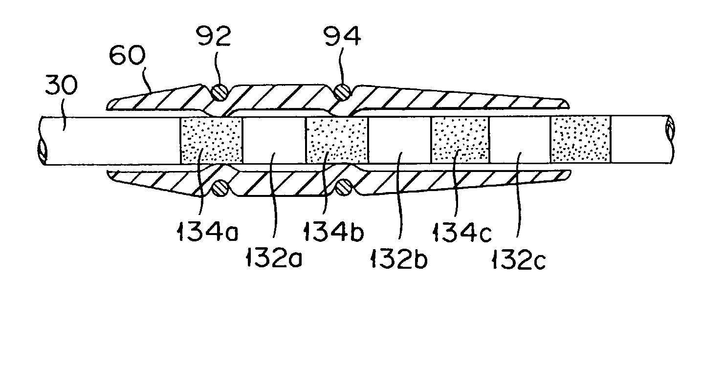
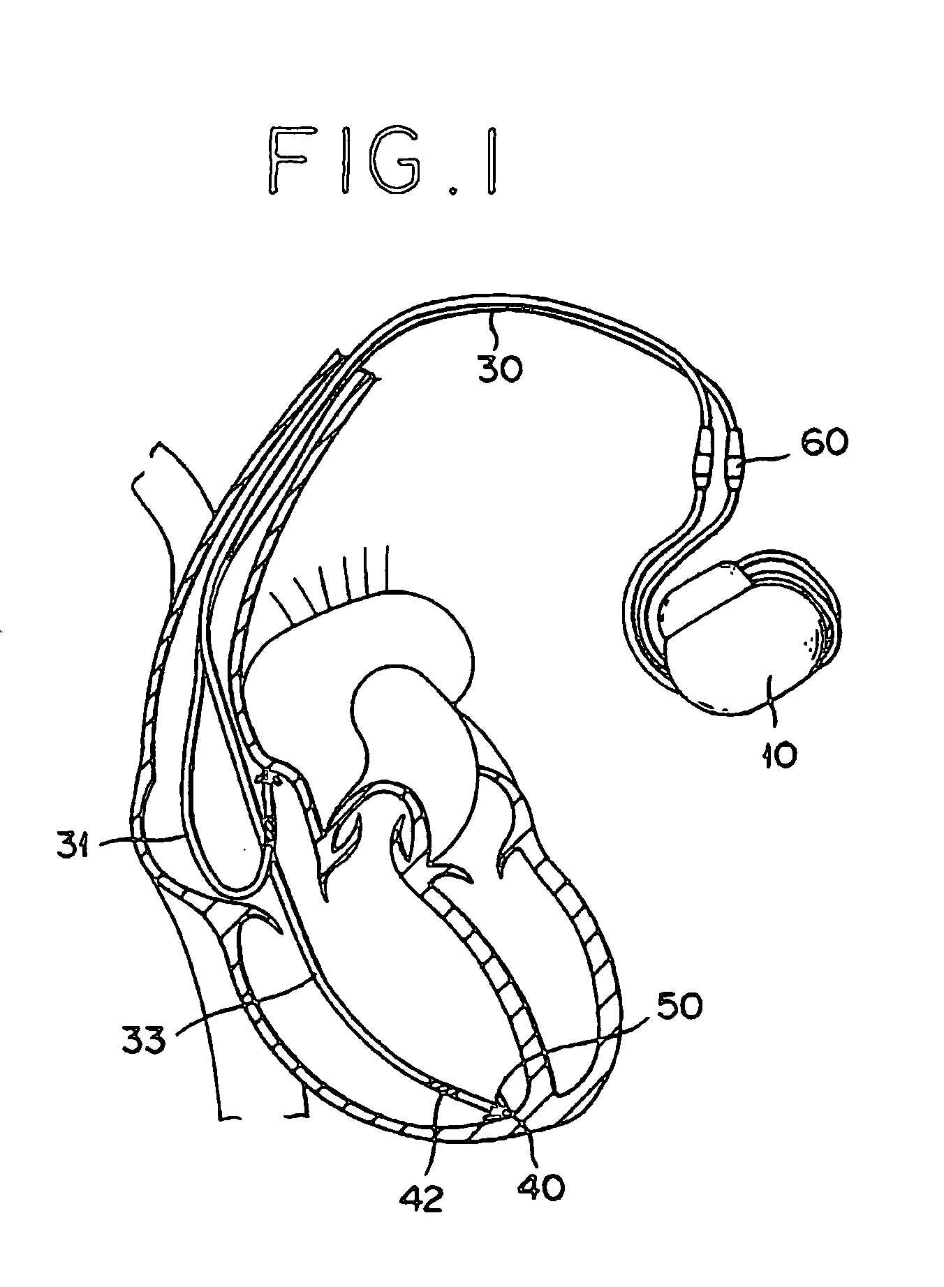
[0049]An implantable electrode lead having a total length of 520 mm and constructed as shown in FIG. 4 was manufactured. This lead was composed of a connecting means 20, a conducting part 30, a tip electrode 40, and a ring electrode 42. An insulating coat 35 for this lead was formed of silicone. This lead comprised a polyvinyl pyrrolidone coat as a lubricating coat layer 34 which extends over 200 mm in length from the ring electrode 42 toward the proximal end and a section 76 of a total length of 100 mm extending over a distance of 300 mm from the ring electrode 42 and continuing into the lubricating coat layer 34 and having regions 132 containing no lubricating coat layer and regions 134 containing a lubricating coat layer formed alternately therein. The pitch 73 of coats was set to be 4 mm and the coat width 71 was set to be 2 mm. The distance between the ligating parts 92 and 94 on the suturing sleeve 60 was set to be 4 mm.

[0050]During the ligation of the lead, the suturing sleev...


PUM


Abstract

An implantable electrode lead excelling in workablity during the introduction and in fastness of fixing by ligation is provided. This implantable electrode lead comprises a lubricating coat layer provided on an insulating coat over a length of at least not less than 100 mm and to a position at a distance of not more than 300 mm from the distal end of the implantable electrode lead. When this lead further comprises on the more proximal end side of the lubricating coat layer a section having regions containing a lubricating coat layer and regions containing no lubricating coat layer formed alternately therein, the workablity during the introduction can be attained and the fastness of fixing by ligation can be also secured.

Description

BACKGROUND OF THE INVENTION[0001]1. Field of the Invention[0002]This invention relates to an implantable electrode lead to be used in conjunction with such an implanted device as a cardiac pacemaker and a defibrillator. More particularly, it relates to a structure of an implantable electrode lead having improved operational efficiency during the course of being implanted in vivo or ligated to a vital tissue by providing at specific portions thereof with a lubricating coat layer.[0003]2. Description of the Related Art[0004]Numerous kinds of implantable electrode leads for the use in conjunction with such an implanted device as a cardiac pacemaker and a defibrillator have been known to the art.[0005]The cardiac pacemaker is a device for electrically stimulating a heart directly thereby increasing a heart rate. There are two types of cardiac pacemakers, namely an external cardiac pacemaker which is disposed outside a patient body and an electrode thereof is introduced into the heart of...

Claims


Application Information

Patent Timeline
IPC IPC(8): A61N1/00A61N1/05
CPCA61N1/056A61N2001/0585A61N2001/0582
Inventor TSUBOI, FUMINORITANAKA, TETSUO
Owner TERUMO KK
Learn More