Method and apparatus for real time clock (RTC) brownout detection

a technology of real-time clock and brownout detection, which is applied in the field of method and apparatus for real-time clock brownout detection, can solve the problems of inaccurateness, consuming valuable processor resources, and gps receiver units with very limited power resources

Inactive Publication Date: 2006-01-10
SAMSUNG ELECTRONICS CO LTD
View PDF18 Cites 56 Cited by
  • Summary
  • Abstract
  • Description
  • Claims
  • Application Information

AI Technical Summary

Problems solved by technology

More particularly, it is related to accurately detecting when a real time clock has become inaccurate due to power brownout.
These conventional schemes typically run continually, thus consuming valuable processor resources.
This is especially disadvantageous in the case of GPS receiver unit with very limited power resources, such as a portable GPS receiver unit.
However, reacquisition of the satellite signals with nearly immediate correlation of the code phase data requires precise time keeping during the period the receiver is off.
In addition, movement of the GPS receiver unit introduces error that may be associated with timing of the PN code signals.
However, the accuracy of a conventional real time clock degrades rapidly below the + / −0.5 ms level due to poor stability and temperature characteristics of typical low cost, low power RTC circuits.
Therefore, even after a very brief time, a hot start is required.
Maintaining accuracy of the various clocking signals in the GPS receiver unit to within ±0.5 ms (one half of a 1 ms code period) is not possible with a conventional GPS oscillator and timing system if the oscillator is powered down between navigation updates.
Under some circumstances, the real time clock may stop altogether due to partial or total loss of the local power source.
Under other circumstances, the RTC may seem normally operational on start-up, but may be inaccurate because it has experienced partial power loss, or a brownout condition that caused the RTC to miss cycles.
For example, a battery used to power the RTC may provide inadequate power levels because it is near the end of its life or because it is subjected to temperatures beyond its operating range.
This is especially problematic when the time from the RTC is transferred to the GPS clocking scheme to support rapid acquisition.
If incorrect RTC time is relied on, incorrect range measurements result.
Using incorrect range measurements in a navigation solution results in an incorrect position calculation.
This is a relatively useless feature.
Prior art methods of RTC failure detection that essentially monitor voltage levels are particularly inadequate when the battery is near its end of life or when the battery is subjected to wide variations in temperature.
Hence, the receiver tries to use the RTC value, assuming it is good, and produces an incorrect solution because the time was in fact in error.
The receiver takes longer to produce a solution, or worse yet, continues to produce bad solutions.
This is difficult for a number of reasons.
Hence, some margin in the threshold has to be provided, shortening the useful battery life.
Even with a margin, some failure events may occur on a statistical basis.

Method used


Image

  • Method and apparatus for real time clock (RTC) brownout detection
  • Method and apparatus for real time clock (RTC) brownout detection
  • Method and apparatus for real time clock (RTC) brownout detection

Examples


Embodiment Construction

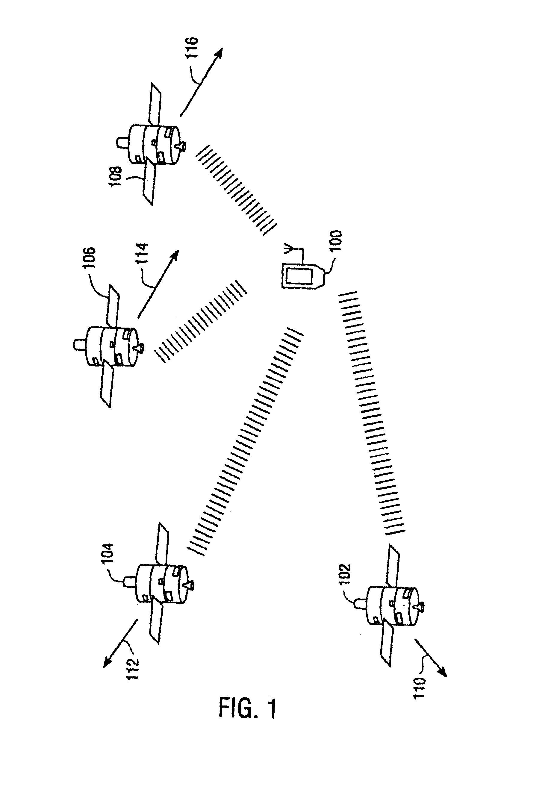
[0030]FIG. 1 illustrates an example environment for operation of a global positioning system (GPS) receiver. FIG. 1 shows a GPS receiver unit 100 and four GPS satellites 102, 104, 106 and 108. Each satellite 102, 104, 106 and 108 is transmitting to the GPS receiver unit 100. Satellite 102 is moving towards the GPS receiver unit 100 along the line of sight (LOS) 110 at a velocity νa+; satellite 104 is moving away from the GPS receiver unit 100 along the LOS 112 at a velocity νb− and satellite 106 is moving away from the GPS receiver 100 along the LOS 106 at a velocity νc−. Consequently, assuming a carrier wavelength of λ, the transmission from satellite 102 experiences a positive Doppler shift of νa+ / λ; the transmission from satellite 104 experiences a negative Doppler shift of νb− / λ; and the transmission from satellite 106 experiences a negative Doppler shift of νc− / λ.

[0031]Satellite 108 is similarly moving away from the GPS receiver unit 100 along the LOS 116 at a velocity νd−. Inf...


PUM


Abstract

A method and apparatus for real time clock brownout detection. A low power real time clock (RTC) operates continuously to keep time in a global positioning system (GPS) receiver while some receiver components are powered down. In various embodiments, a brownout detector circuit detects a loss of RTC clock cycles. If a loss of RTC clock cycles exceeds a predetermined threshold such that the RTC is not reliable for GPS navigation, an RTC status signal so indicates.

Description

RELATED APPLICATIONS[0001]This application is a continuation-in-part of U.S. patent application Ser. No. 10 / 021,119, entitled “Calibrated Real Time Clock for Acquisition of GPS Signals During Low Operation”, filed Oct. 30, 2001, now U.S. Pat. No. 6,662,107, which is hereby incorporated by reference.FIELD OF THE INVENTION[0002]This invention is generally related to Global Positioning System (GPS) receivers. More particularly, it is related to accurately detecting when a real time clock has become inaccurate due to power brownout.BACKGROUND[0003]The Global Positioning system (GPS) is a collection of twenty-four earth-orbiting satellites. Each of the GPS satellites travels in a precise orbit about 11,000 miles above the earth's surface. A GPS receiver locks onto at least three of the satellites to determine its precise location. Each satellite transmits a signal modulated with a unique pseudo-noise (PN) code. Each PN code is a sequence of 1023 chips that are repeated every ms consisten...

Claims


Application Information

Patent Timeline
Patent Type & Authority Patents(United States)
IPC IPC(8): G01S5/02G01C21/26G01R19/165G01S1/00G01S19/23G01S19/34G04C10/04G04F5/00G04G19/12G06F1/14G06F1/30G06F1/32
CPCG01R19/16542G01S19/23G01S19/235G01S19/34G04C10/04G04G19/12G06F1/14G06F1/30G06F1/3203G06F1/3287G04F5/00Y02B60/1282Y02D10/00G01C21/26
Inventor GRONEMEYER, STEVEN A.
Owner SAMSUNG ELECTRONICS CO LTD
Why Eureka
Try Eureka