
Conveyor belt cleaner scraper blade with sensor and control system therefor

Inactive Publication Date: 2006-01-17
MARTIN ENG
View PDF25 Cites 52 Cited by
  • Summary
  • Abstract
  • Description
  • Claims
  • Application Information

AI Technical Summary

Benefits of technology

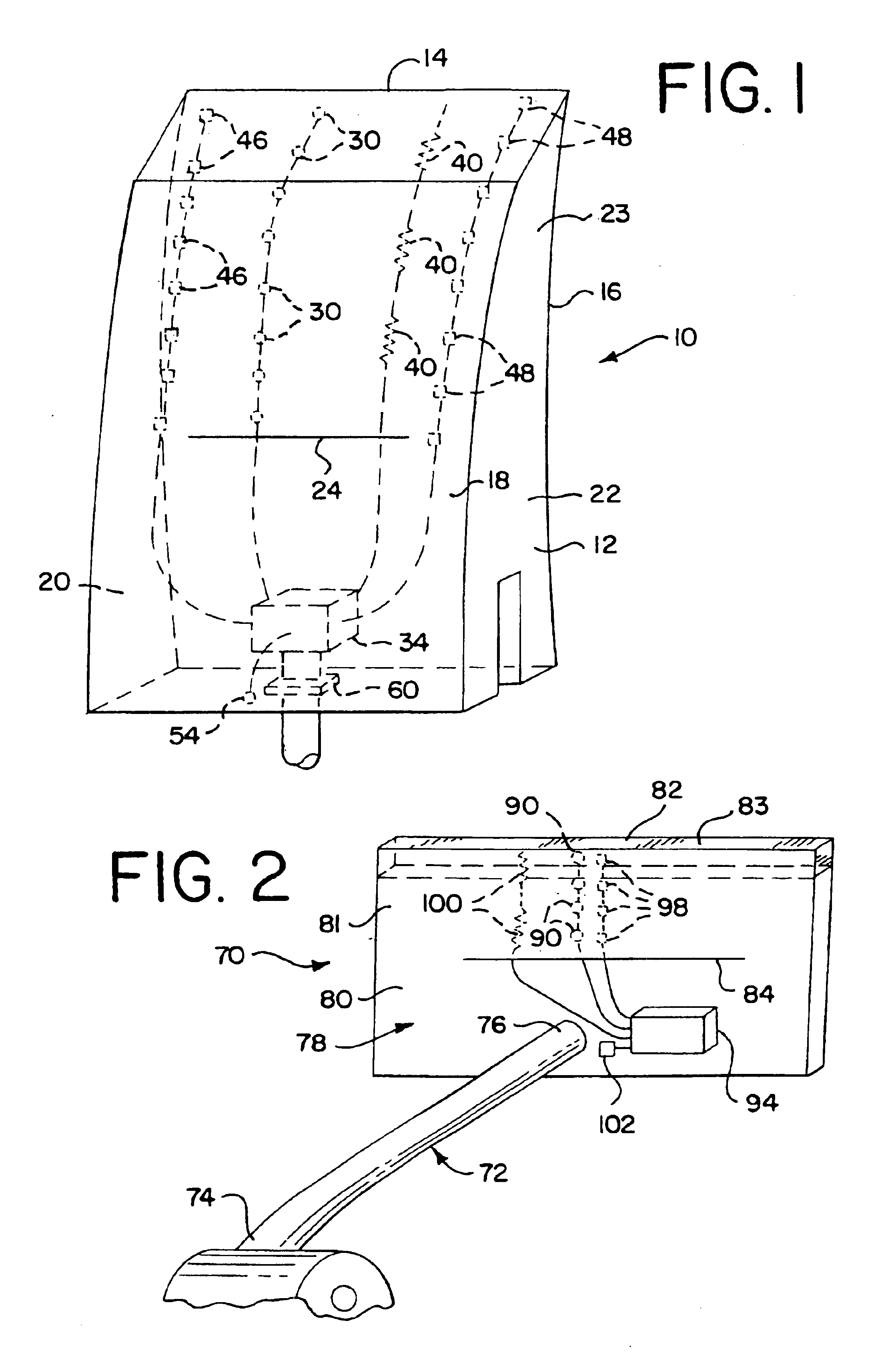
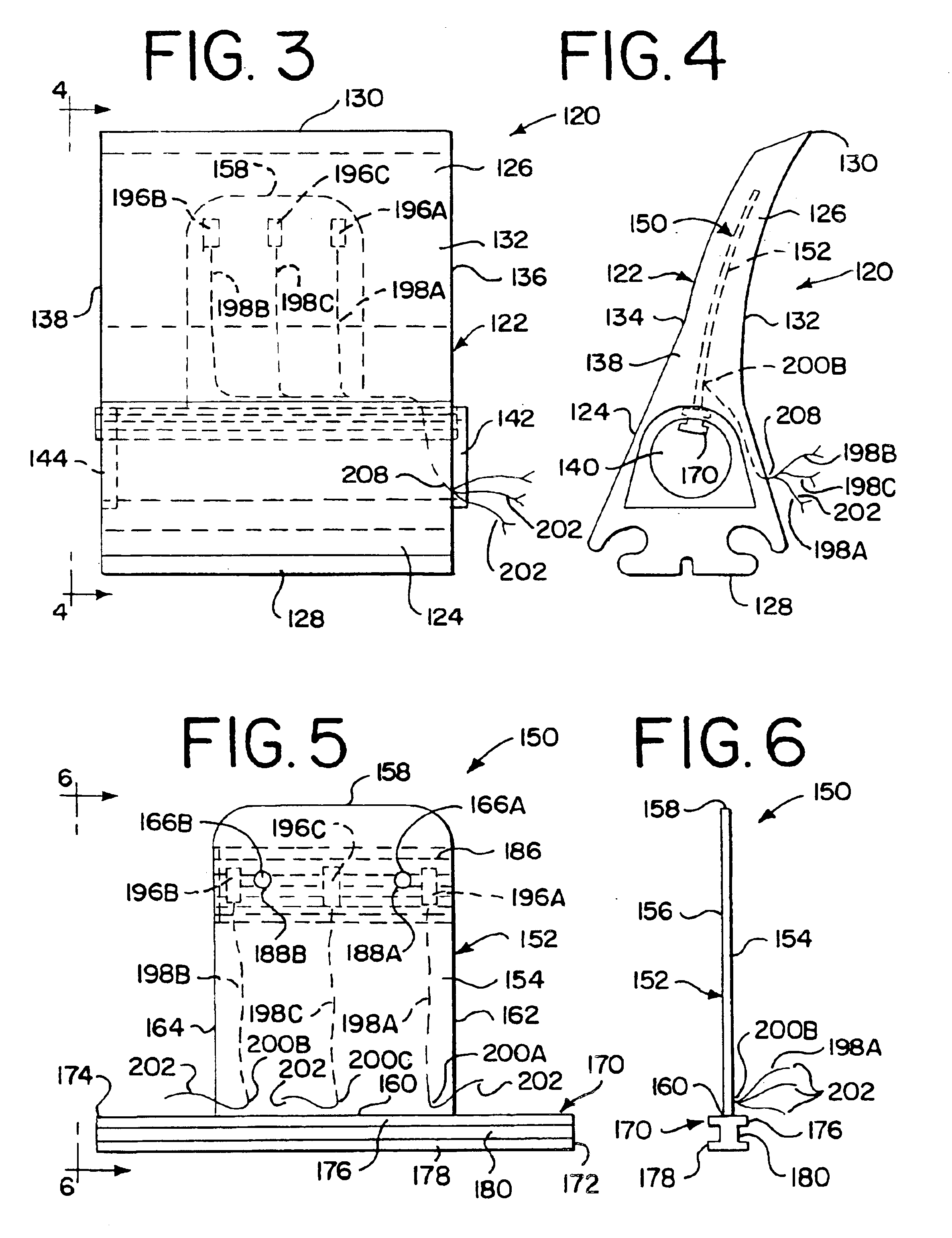
[0007]A two-piece scraper blade assembly is disclosed that enhances removability of the scraper blade tip in the event that replacement becomes necessary, as well as providing a secure mounting mechanism to retain the blade tip in position during normal operation. An alternative sensor arrangement is also presented incorporating a unique strain sensor configuration that provides a larger and more informative signal output than prior installations.
[0011]The sensors provided in the cleaning blade are specifically arranged to take advantage of the sensing techniques used, and previous research conducted, on the behavior of various polyurethane compounds. The tip and base materials are chosen to give acceptable deflection / stress levels at the sensing element. The interlocking features of the base and tip provide strong electrical signals as well as preventing base / tip separation during cleaner operation. Replaceable / wearable tips have been incorporated in the present invention for functionality, simplicity, and to reduce the cost of replacing relatively expensive blade vibration elements.

Problems solved by technology

During operation, the scraping edge of each scraper blade wears due to its scraping engagement with the rotating conveyor belt.
If the scraper blades are biased against the conveyor belt with an excessive amount of force, this will result in excessive wear to the scraper blades, potential damage to the conveyor belt, and may cause the tip of the scraper blade to develop an excessively high temperature due to the friction generated between the scraper blade and the rotating conveyor belt.
If the scraper blades are biased against the conveyor belt with too small of a force, the scraper blades may not effectively clean the conveyor belt.
In addition, the scraping tip of the scraper blades may vibrate or chatter against the conveyor belt depending upon the amount of force with which the scraper blades are biased into engagement with the conveyor belt, thereby potentially damaging the scraper blades and / or the belt, and decreasing cleaning efficiency.

Method used


Image

  • Conveyor belt cleaner scraper blade with sensor and control system therefor
  • Conveyor belt cleaner scraper blade with sensor and control system therefor
  • Conveyor belt cleaner scraper blade with sensor and control system therefor

Examples


Embodiment Construction

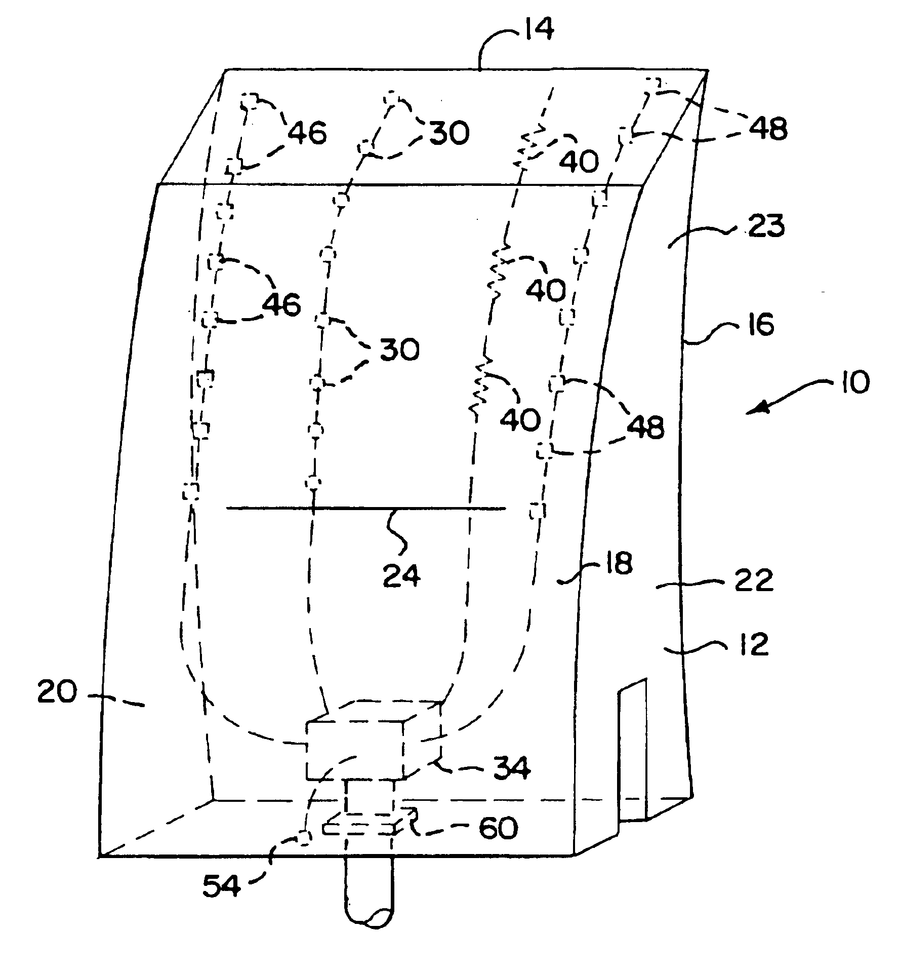
[0052]The primary conveyor belt cleaner scraper blade 10 of the present invention, as shown in FIG. 1, is adapted to be removably attached to a cross shaft (not shown) of a conveyor belt cleaner for engagement with the conveyor belt proximate the head pulley such as disclosed in U.S. Pat. No. 4,598,823 of Martin Engineering Company, which is incorporated herein by reference. One or more scraper blades 10 may be attached to the cross shaft. A tensioning device, such as disclosed in U.S. Pat. No. 5,088,965 of Martin Engineering Company, which is incorporated herein by reference, is attached to the end of the cross shaft and is adapted to provide selective conjoint movement (either rotational or linear) of the cross shaft and of the scraper blades 10 to move each scraper blade 10 into biased scraping engagement with the conveyor belt with a scraping force.

[0053]The scraper blade 10 includes a base member 12 that is adapted to be removably attached to the cross shaft in any of a number ...


PUM

PropertyMeasurementUnit
Lengthaaaaaaaaaa
Forceaaaaaaaaaa
Angleaaaaaaaaaa

Abstract

A conveyor belt cleaner scraper blade for cleaning the surface of a conveyor belt and a method of manufacture of the scraper blade. The scraper blade includes a body having a base member adapted to be attached to a cross shaft of a conveyor belt cleaner and a scraping member which extends outwardly from the base member to a scraping tip. The scraper blade includes one or more electrical sensors that are embedded in an insert member. The insert member and the sensors are molded and embedded within the body of the scraper blade. Each of the sensors is adapted to provide an electrical output signal representing a physical condition of the scraper blade sensed by the sensor. A variety of sensor embodiments are described, as well as two embodiments of control and monitoring systems for use in conjunction with the various blade and sensor combinations.

Description

RELATED APPLICATIONS[0001]This application is a continuation-in-part of U.S. application Ser. No. 10 / 025,091, filed Dec. 19, 2001, now U.S. Pat. 6,597,969, which is a continuation-in-part of U.S. application Ser. No. 09 / 454,856, filed Dec. 7, 1999, now U.S. Pat. No. 6,374,990, which claims the benefit of U.S. Provisional Application No. 60 / 111,774, filed Dec. 10, 1998.BACKGROUND OF THE INVENTION[0002]The present invention is directed to a conveyor belt cleaner scraper blade for scraping adherent material from a conveyor belt, and in particular to a conveyor belt cleaner scraper blade including one or more sensors for monitoring the operating conditions of the scraper blade and control system therefore.[0003]Some conveyor mechanisms utilize a moving conveyor belt to transport sand, gravel, coal and other bulk materials, from one location to another. As the bulk material is discharged from the conveyor belt, a portion of the material often remains adhered to the belt. Conveyor belt cl...

Claims


Application Information

Patent Timeline
IPC IPC(8): B65G45/12B23H9/00B23H9/02B23K1/018B65G45/16H01L21/48
CPCB65G45/12B65G45/16B65G2203/042B65G2203/02
Inventor SWINDERMAN, R. TODDWATERS, ANDREW J.PEREZ, PABLO F.DIETSCH, PHILLIP E.
Owner MARTIN ENG
Learn More