
Hardened rotary cutting tip

a cutting tip and hardened technology, applied in the field of hardened rotary cutting tips, can solve the problems of increasing the frequency with which tools must be replaced, reducing the useful life of the tool body, and reducing the desirable product of the tool for such machines, so as to facilitate the rotation of the tool and maximize the useful life of the tool

Active Publication Date: 2006-01-17
THE SOLLAMI COMPANY
View PDF9 Cites 21 Cited by
  • Summary
  • Abstract
  • Description
  • Claims
  • Application Information

AI Technical Summary

Benefits of technology

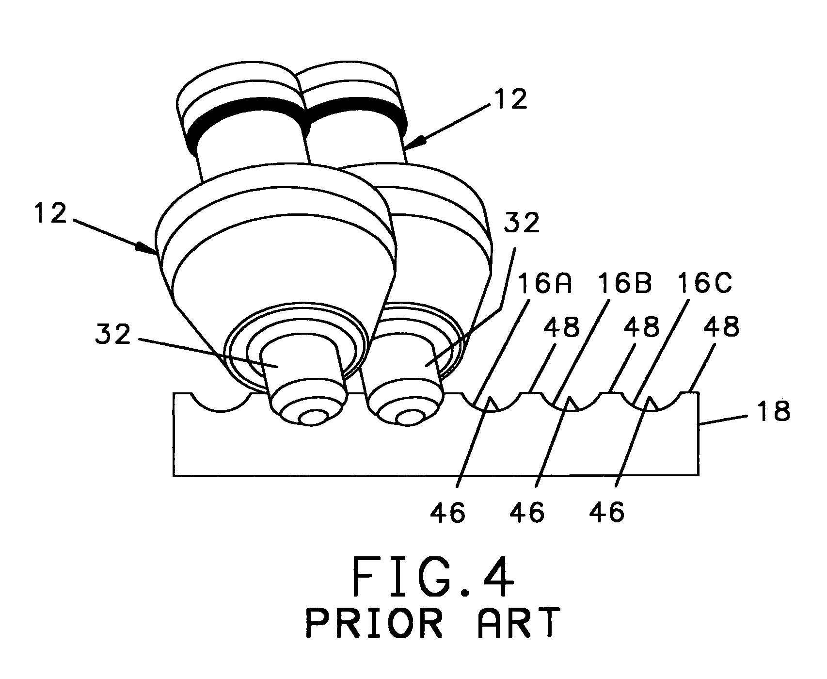
[0012]Since the machines used to cut hard surfaces employ numerous tools, tool manufacturers have continuously strived to minimize the cost of manufacturing the tool while maximizing the useful life thereof. Since the most expensive portion of such cutting tools is the tungsten carbide insert or tip fitted in the seat at the forward end of the tool, it is desirable that the mass of the tip be minimized. On the other hand, if the tool is manufactured with an undersized cutting tip, the tip will become worn away long before the tool body, thereby increasing the frequency with which the tools must be replaced and rendering the tool a less desirable product for such machines. Years of development of such tools have resulted in a standardization of the diameter of the base of the tungsten carbide tips or inserts at the forward end of the tools used in the milling industry of between 0.690 inch to 0.750 inch. The standardization of the base diameter of such tips or inserts occurred as the result of the efforts of manufacturers to reach that perfect balance in which the useful life of the tungsten carbide tip equals the useful life of the metal tool body on which the tungsten carbide tip is mounted. In similar fashion, the tips used at the forward end of the tools of trenching machines, and the tools for rock saws and the like have also become standardized over the years, where the standardization has occurred to maximize the useful life of both the cutting tip and the tool body in which it is mounted.
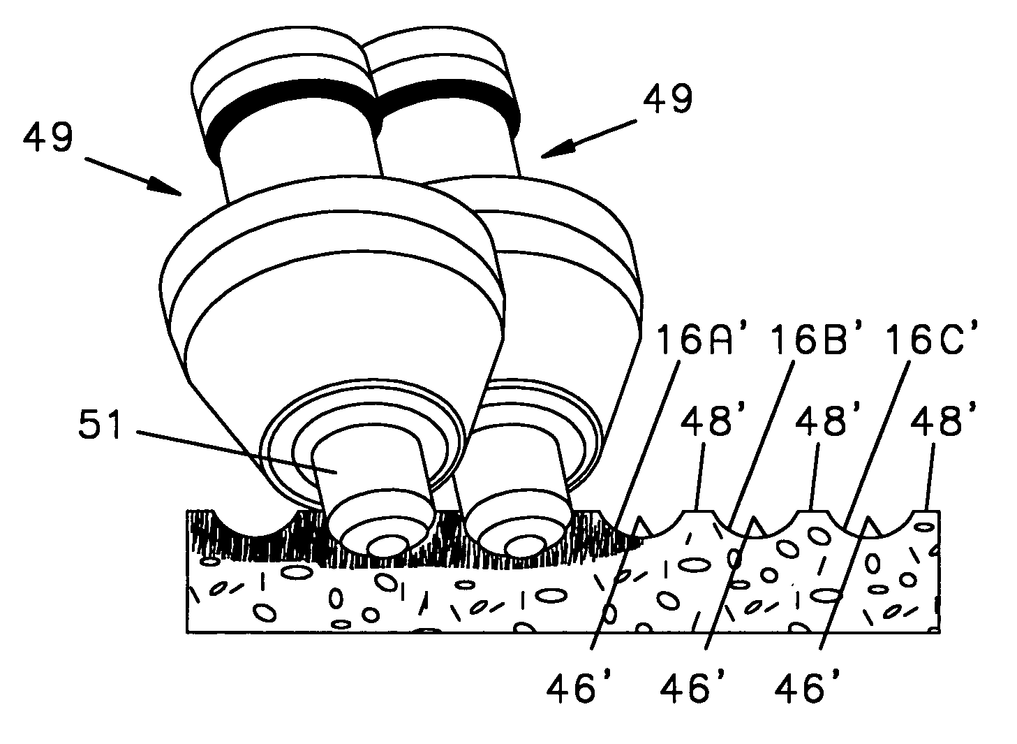
[0015]I have observed, however, that by providing an insert with a base having an enlarged diameter, the diameter being significantly larger than the standard 0.690 diameter for tips currently used in milling machines, the ridges formed between the valleys cut by the tips will be reduced in size. This occurs because a portion of the outer circumference of the base of the carbide insert breaks off peaks extending from the upper portion of the ridge thereby reducing the relative elevation of the ridges between the adjacent valleys. The reduction of the ridges alters the direction of loosened particles and directs them away from the metal body of the tools and reduces washaway of the tool body.
[0019]The advantages of the insert of the present invention are further enhanced by providing a plurality of notches in the circumference of the base, the notches extending from the radially extending planar forward surface of the base to a rearward surface of the base such that the outer portion of the base is divided into a plurality of spaced flanges. The provision of the notches allows particles of hardened material loosened by the cutting tip to erode grooves in the tool body behind the cutting tip corresponding to the notches. The grooves in the tool body serve to channel particles of loosened material along the tool body without causing further washaway of the tool body. The grooves which become worn in the tool body may also facilitate rotation of the tool, thereby insuring that the cutting tip of the tool becomes evenly worn around the circumference thereof so as to maximize its useful life. The flanges that make up the outer portion of the base shield the remaining circumference of the tool body from erosion or washaway.

Problems solved by technology

On the other hand, if the tool is manufactured with an undersized cutting tip, the tip will become worn away long before the tool body, thereby increasing the frequency with which the tools must be replaced and rendering the tool a less desirable product for such machines.
I have discovered, however, that providing a cutting tool having a carbide insert with an abnormally large diameter base will enhance the useful life of the tool because washaway of the tool body is reduced.
As a result of this orientation, the particles of hardened material loosened by the cutting tip will move along the body of the cutting tool and cause washaway which gradually erodes the tool body.

Method used


Image

  • Hardened rotary cutting tip
  • Hardened rotary cutting tip
  • Hardened rotary cutting tip

Examples


Embodiment Construction

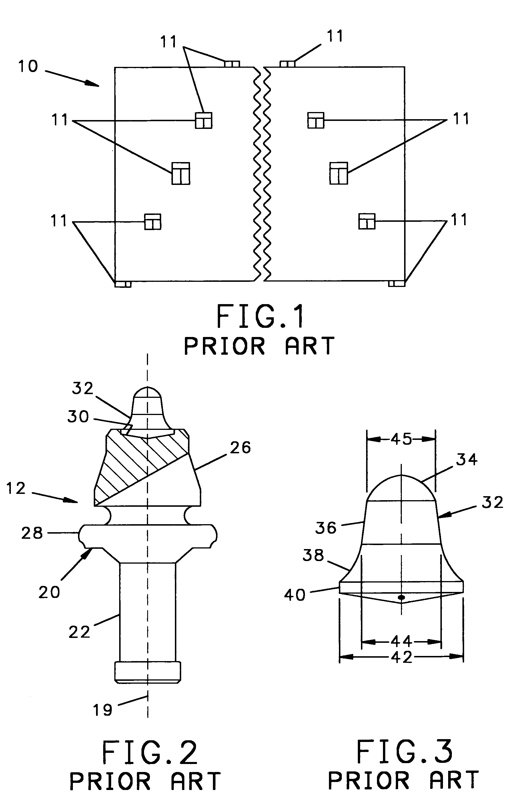
[0054]Referring to FIGS. 1, 2, and 4, a milling machine employs a rotatable drum 10 on which are a plurality of tool mountings for mounting a plurality of cutting tools 12 with the cutting tools 12 positioned in a spiral around the circumference of the drum 10. Each of the tools 12 is mounted to the drum 10 such that the forward cutting end of the tool 12 will cut a groove in the hard surface 18 of the material such as concrete or asphalt. By mounting the tools 12 in a spiral around the circumference of the drum 10, the cutting ends of the various tools 12 are positioned to form a plurality of adjacent grooves 16A, 16B, 16C as the drum 10 rotates adjacent the hard surface 18.

[0055]Each of the tools 12 is mounted on the drum 10 to engage the hard surface 18 at an up angle of approximately 45 degrees and a side angle of seven degrees. The tools 12 are also retained in holders 11 on the drum 10 so as to be rotatable about the longitudinal axis 19 of the tool 12 such that the tool 12 we...


PUM

PropertyMeasurementUnit
Fractionaaaaaaaaaa
Angleaaaaaaaaaa
Diameteraaaaaaaaaa

Abstract

An insert for a cutting tool has a conical cutting tip, and axially behind the cutting tip is a mid-section. Behind the mid-section is a cylindrical base. Where the insert is for use on a tool of a milling machine, the base has a diameter of at least 0.800 inch so as to be considerably larger than the standard base of inserts currently in use on such machines. The enlarged base protects the tool body to which the insert is attached from washaway. The invention is useable in other industries employing rotary cutting tools. In other industries, the insert is made with an enlarged diameter base so as to protect the tool body behind the insert from erosion or washaway. Indentations in the outer circumference of the base improve the rotation of the tool and provide channels through which loosened particles of hard material are directed, thereby further reducing erosion of the tool body.

Description

[0001]The applicant claims priority from his provisional application filed Nov. 3, 2003 and assigned Ser. No. 60 / 516,886. The present invention relates to the cutting tips of rotary mounted tools and, in particular, to an improved tip which will prolong the useful life of the tool.BACKGROUND OF THE INVENTION[0002]Machines that remove the upper layer of pavement from a concrete road employ a plurality of cutting tools mounted on a drum, with each of the tools rotatable about its longitudinal axis. When such machines are employed to remove the upper surface of a road, the tools become worn and must be periodically replaced. Depending upon weather conditions, it may be necessary to replace the tools mounted on the drum of such machines daily, and sometimes twice daily. The drums of such machines typically mount more than one hundred of such tools, and therefore, the machines that remove the upper surface from a road must be removed from service for a lengthy period of time while the to...

Claims


Application Information

Patent Timeline
IPC IPC(8): E21C37/10
CPCB28D1/188E21C2035/1816E21C35/1837
Inventor SOLLAMI, PHILLIP A.
Owner THE SOLLAMI COMPANY
Learn More