Multiple output converter with improved cross regulation

a multi-output converter and cross-regulation technology, applied in the direction of electric variable regulation, process and machine control, instruments, etc., can solve the problems of secondary windings b>12/b>, b>14/b> and output chokes b>50/b>, and the output chokes cannot be ideally coupled without leakage, so as to improve the cross-regulation of multiple-output converters.

a multi-output converter and cross-regulation technology, applied in the direction of electric variable regulation, process and machine control, instruments, etc., can solve the problems of secondary windings b>12/b>, b>14/b> and output chokes b>50/b>, and the output chokes cannot be ideally coupled without leakage, so as to improve the cross-regulation of multiple-output converters.

US6987679B2Inactive Publication Date: 2006-01-17DELTA ELECTRONICS INC

Image

  • Multiple output converter with improved cross regulation
  • Multiple output converter with improved cross regulation
  • Multiple output converter with improved cross regulation

Examples


Embodiment Construction

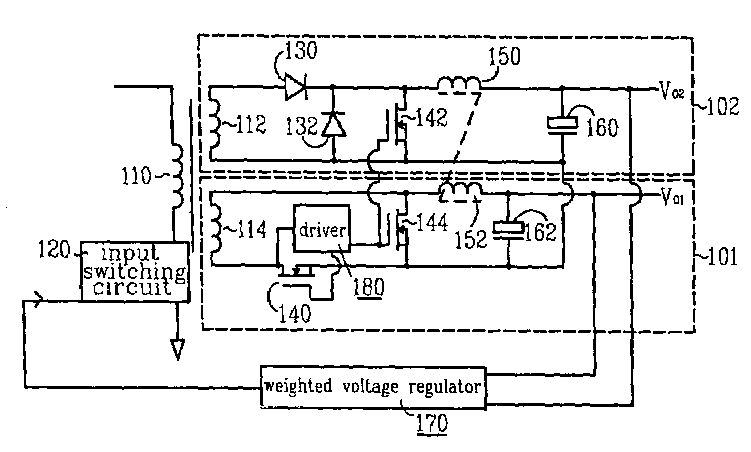
[0027]Referring to FIG. 5, it illustrates a schematic diagram of a two outputs converter with improved cross regulation according to a first alternate embodiment of the present invention. The converter includes a transformer having the primary winding 110 coupled to the input switching circuit 120, the first secondary winding 114 and the second secondary winding 112. The input switching circuit 120 includes at least one power switch (unshown). The converter further includes a first output channel including a synchronous rectifier connected to the first secondary winding 114 for providing a first output voltage Vo1, and a second output channel including a diode rectifier connected to the second secondary winding 112 for providing a second output voltage Vo2. The synchronous rectifier of the first output channel includes the forward MOSFET 140 and the freewheeling MOSFET 144. The diode rectifier of the second output channel includes the forward diode 130 and the freewheeling diode 132...


PUM


Abstract

A cost effective circuit improves the cross regulation of multiple outputs converter, especially for that output chokes are coupled and a synchronous rectifier is applied to one of the outputs. A DC / DC converter includes a transformer having a primary winding and two secondary windings. The first secondary winding is coupled to a synchronous rectifier and a first output choke. The second secondary winding is coupled to a diode rectifier and a second output choke. The first output choke and the second output choke are coupled. A low power MOSFET switch is added to the diode rectifier for avoiding the diode rectifier operating in DCM when light loaded.

Description

BACKGROUND OF THE INVENTION[0001]1. Field of the Invention[0002]This invention relates to output rectifier circuits of switching mode power supply, and more particularly to multiple outputs converter with synchronous rectifier and diode rectifier applied simultaneously.[0003]2. Description of the Prior Art[0004]DC / DC converters are commonly used to provide power for electronic devices such as computers, communication devices and personal digital assistants. A DC / DC converter converts a DC input voltage to a conditioned DC output voltage and then provides one or multiple output DC voltages. For example, for personal computer and networking applications, a DC / DC converter may be employed to convert a DC input voltage to provide three main output voltages (12V DC, 5V DC and 3.3V DC).[0005]FIG. 1 illustrates a conventional multiple outputs forward converter. The forward converter includes the main power switch 20 coupled to the primary winding 10 of a transformer. In the illustrated emb...

Claims


Application Information

Patent Timeline
17 Jan 2006
Publication
US6987679B2
IPC
H02M7/217; H02M3/145; H02M3/28; H02M3/335
CPC
H02M3/33592; Y02B70/1475; H02M2001/009; Y02B70/10; H02M1/009
Inventors
GAN, HONGJIAN; DOU, SEN