Grating dispersion compensator and method of manufacture

a compensator and dispersion technology, applied in the direction of instruments, optical waveguide light guides, optics, etc., can solve the problems of fixed dispersion value compensators, methods that are not easily tunable, and temporal broadening

Inactive Publication Date: 2006-01-17
BROADCOM INT PTE LTD
View PDF18 Cites 84 Cited by
  • Summary
  • Abstract
  • Description
  • Claims
  • Application Information

AI Technical Summary

Problems solved by technology

A problem related to this growing wavelength band of optical pulses is temporal broadening due to chromatic dispersion.
Generally, these methods are not easily tunable and, therefore, can only be used for compensating fixed dispersion values.
It is impractical to design a specific DCF or fiber Bragg grating for every possible chromatic dispersion due to various lengths of optical fiber or other optical components in a communications signal.
This also may be a problem for fixed dispersion compensation devices such as DCF's or fiber Bragg gratings.

Method used


Image

  • Grating dispersion compensator and method of manufacture
  • Grating dispersion compensator and method of manufacture
  • Grating dispersion compensator and method of manufacture

Examples


Embodiment Construction

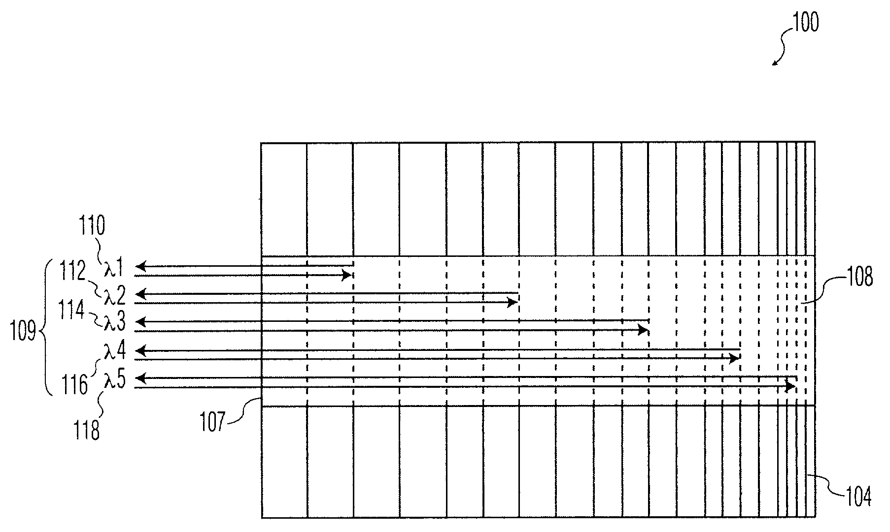
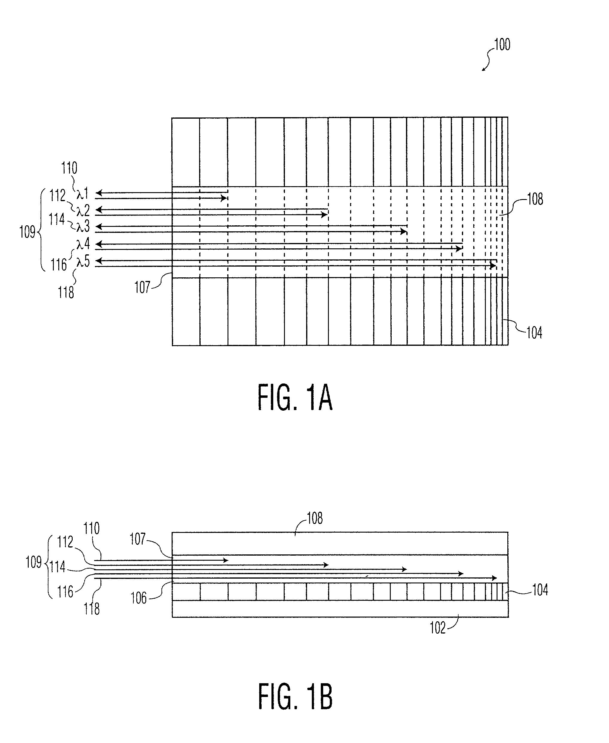
[0054]One exemplary embodiment of the present invention, illustrated in FIGS. 1A and 1B, is GDC 100 including chirped optical grating 104. FIG. 1A is a top plan drawing and FIG. 1B is a side plan drawing of GDC 100. The exemplary device includes substrate 102, chirped optical grating 104, wave guide 106, and passivation layer 108. Waveguide 106 desirably exhibits low optical loss and a relatively high index of refraction in the desired wavelength band. Although the exemplary devices described in the present application are formed from various III / V materials, such as InP, GaAs, AlGaAs, or InGaAsP, other possible materials choices are contemplated. Possible alternative materials for waveguide 106 include: doped silica (similar to optical fibers); silicon; germanium; and other dielectric materials, which have low optical loss characteristics for the desired wavelength band and a relatively easily variable index of refraction.

[0055]Passivation layer 108 and chirped optical grating 104,...


PUM


Abstract

A grating dispersion compensator (GDC), including: a substrate; a dielectric grating layer; a planar waveguide; and a passivation layer. The dielectric grating layer may be formed on the substrate and includes a variation in refractive index. This variation in refractive index defines a grating period. The grating period may vary along the longitudinal axis of the GDC according to a predetermined function. A selected center wavelength and dispersion curve may be created. The chirp of the grating period may be controlled by current, voltage, temperature, or pressure. The planar waveguide is formed on the dielectric grating layer and includes an input / output (I / O) surface normal to the longitudinal axis of the planar waveguide. The passivation layer is formed on the planar waveguide. Alternatively, a GDC may be formed with the dielectric grating layer on top of the planar waveguide rather then beneath it.

Description

CROSS-REFERENCE TO RELATED APPLICATIONS[0001]This application claims the benefit of U.S. Provisional Application No. 60 / 314,951, filed Aug. 24, 2001, the contents of which are incorporated herein by reference.[0002]This invention relates to grating dispersion compensators. More particularly this invention relates to dispersion compensation gratings integrally formed within planar waveguide apparatuses.BACKGROUND OF THE INVENTION[0003]Optical communication systems use pulses of light to transmit data. The light used to create these pulses necessarily contains a band of wavelengths, rather than a single wavelength, even though the light is generally from laser sources. A broadening of the wavelength band occurs when the light is pulsed, due to conditions imposed by the Fourier transform spectrum of the pulse shape. Some devices, such as electro-absorption modulators (EAM's), used to generate the pulses broaden the wavelength band of the light even further than the transform limit. The...

Claims


Application Information

Patent Timeline
Patent Type & Authority Patents(United States)
IPC IPC(8): G02B6/34G02B6/12
CPCG02B6/12007G02B6/29395G02B6/29394G02B6/29325G02B2006/12107G02B6/29398
Inventor BOND, AARONJAMBUNATHAN, RAMFRATESCHI, NEWTON C.
Owner BROADCOM INT PTE LTD
Why Eureka
Try Eureka