
Ultra-low permeation hose and method of manufacture

a technology of permeation hose and hose body, which is applied in the direction of layered products, mechanical equipment, chemical equipment and processes, etc., can solve the problems of inability to conform to the rubber hose, inconvenient hoses, and leakage of refrigerant, and achieve excellent heat resistance and adhesion, excellent heat resistance and co2 permeation resistance, and excellent resistance to refrigerant permeation.

Inactive Publication Date: 2006-01-24
THE YOKOHAMA RUBBER CO LTD +1
View PDF16 Cites 19 Cited by
  • Summary
  • Abstract
  • Description
  • Claims
  • Application Information

AI Technical Summary

Benefits of technology

The solution provides ultra-low permeation hoses with excellent resistance to refrigerant and CO2 permeation, maintaining integrity under deformation and high temperatures, suitable for automotive air conditioning applications.

Problems solved by technology

The refrigerant used until now has been the hydrofluorocarbon R134a, but R134a has a global warming potential (GWP) relative to CO2 of about 3,100, which represents a major problem.
However, because the metal vapor-deposited film is very thin, it is unable to conform to the rubber hose as the hose undergoes large deformation during use.
As a result, pinholes and cracks arise in the metal vapor-deposited film, allowing the refrigerant to leak out.
Such hoses are particularly unsuitable as ultra-low permeation hoses when CO2 is the refrigerant.
When the laminated film composed of metal foil and plastic film described in JP 2-80881 A is used, deformation of the rubber hose causes the metal foil to rupture, making it impossible to maintain a low permeability to refrigerants.
Moreover, JP 2-80881 A fails to specifically mention a method for bonding the metal foil with the plastic film, the bonding of which is generally difficult, or a method for bonding the nylon tubing serving as the inner layer of the hose with the barrier layer.
However, the adhesive layer in a metal (aluminum)-strength-retaining layer (nylon) construction bonded using an aromatic polyester adhesive ultimately fails when exposed to supercritical CO2.

Method used


Image

  • Ultra-low permeation hose and method of manufacture
  • Ultra-low permeation hose and method of manufacture

Examples


example 1

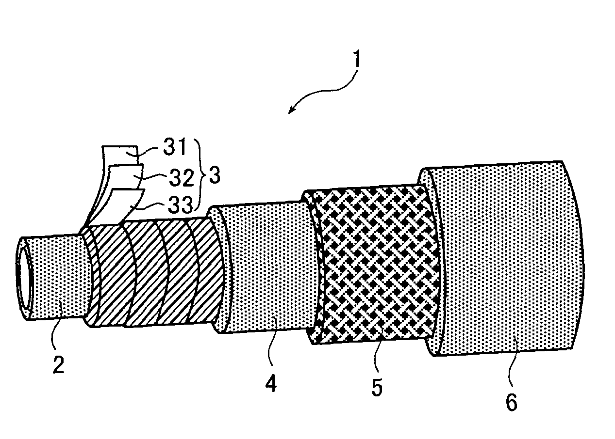
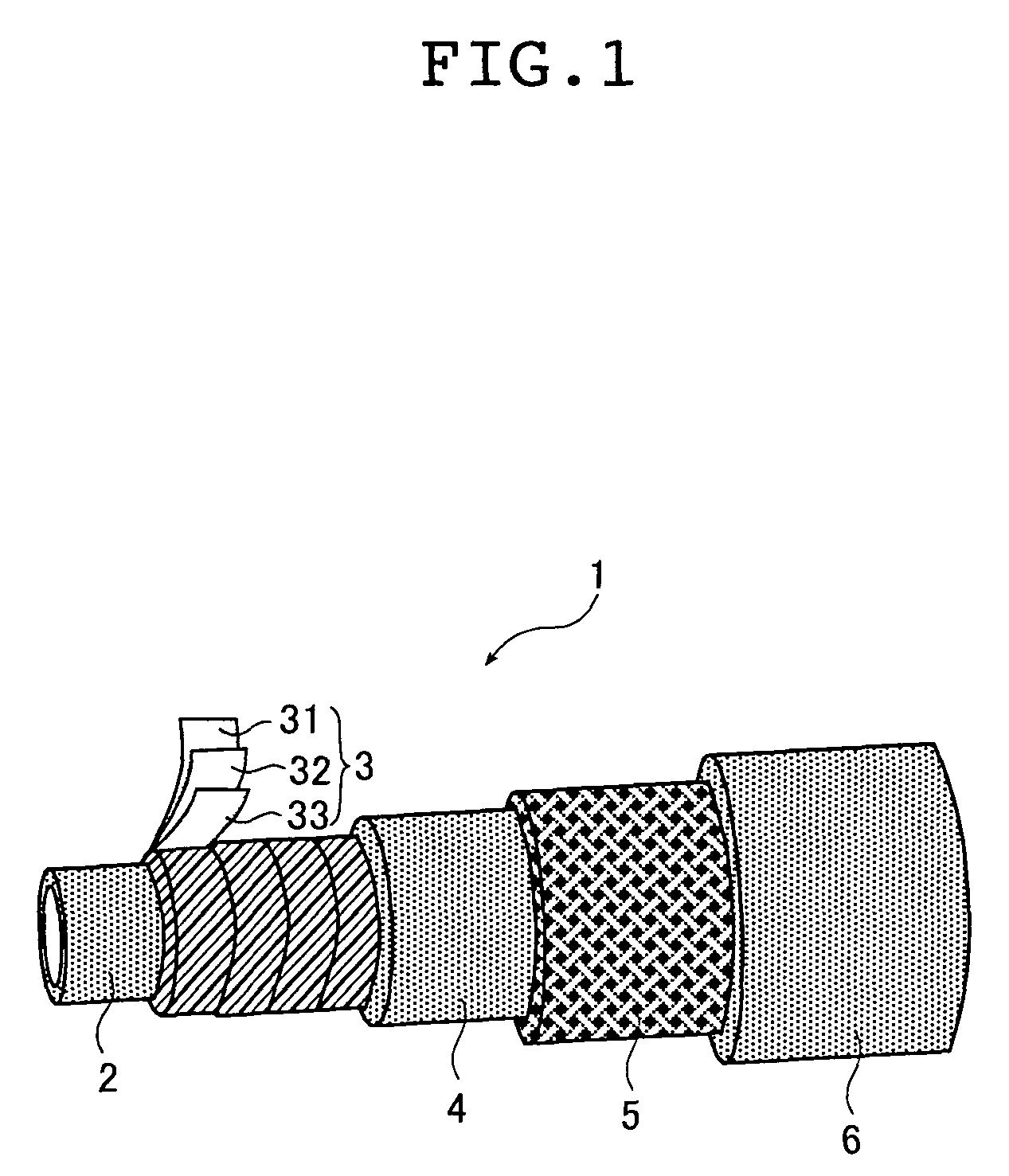
[0121]The nylon 6 serving as the innermost layer resin was extruded about the outer periphery of a 6 mm diameter mandrel from an extruder having a crosshead die for resin, thereby forming an innermost layer having a thickness of 0.2 mm. A phenolic adhesive was then applied to the extruded resin layer and the laminated film A was spirally wound in a half-wrap arrangement—that is, so that each turn of the film overlapped the underlying turn by one-half of the film width—on top while applying phenolic adhesive thereto, in this way forming a refrigerant barrier layer having a thickness of 0.2 mm.

[0122]The HNBR rubber composition serving as the inner tube rubber composition was then extruded over the refrigerant barrier layer using an extruder having a crosshead die for rubber, thereby forming an inner tube outer layer having a thickness of 1.6 mm. A reinforcement made of aramid yarn was braided (1500 d, 80 yarns) over the inner tube outer layer so as to form a reinforcing layer. The EPD...


PUM

PropertyMeasurementUnit
elongation at breakaaaaaaaaaa
thicknessaaaaaaaaaa
thicknessaaaaaaaaaa

Abstract

An object of the present invention is to provide ultra-low permeation hoses which have at the interior thereof a refrigerant barrier layer that consists in large part of a metal layer and is capable of conforming to hose deformation, which have an excellent resistance to refrigerant permeation (i.e., barrier properties to refrigerants), particularly an excellent CO2 permeation resistance and an excellent heat resistance when CO2 is used as the refrigerant. The object can be accomplished by an ultra-low permeation hose having at least a refrigerant barrier layer and a rubber layer and / or a resin layer; wherein the refrigerant barrier layer is a laminated film comprising a resin layer and, on the outside thereof, a metal layer, which the resin layer and the metal layer are bonded together by a polyamide-epoxy reactive adhesive.

Description

BACKGROUND OF THE PRESENT INVENTION[0001]1. Field of the Present Invention[0002]The present invention relates to ultra-low permeation hoses and to a method of manufacture thereof. The present invention relates in particular to ultra-low permeation hoses having an increased resistance to permeation by such substances as refrigerants, fuel gases and flame cutting gases, and also having heat resistance and resistance to carbon dioxide permeation (referred to hereinafter as “CO2 permeation resistance”), as well as to a method of manufacturing such hoses.[0003]2. Description of the Related Art[0004]The hoses used for carrying refrigerant in automotive air conditioning units and similar applications generally have an inner tube that includes polyamide resin or modified butyl rubber as a refrigerant barrier layer. The refrigerant used until now has been the hydrofluorocarbon R134a, but R134a has a global warming potential (GWP) relative to CO2 of about 3,100, which represents a major probl...

Claims


Application Information

Patent Timeline
Patent Type & Authority Patents(United States)
IPC IPC(8): F16L11/04F16L11/08B32B1/08B32B15/08F16L11/12F16L11/14
CPCB32B1/08F16L11/14B32B15/08
Inventor OISHI, HIDEYUKIKAWAMORI, YUUJISHIBANO, HIROAKITASHIRO, FUMIO
Owner THE YOKOHAMA RUBBER CO LTD
Learn More