Channeled flat plate fin heat exchange system, device and method

Active Publication Date: 2006-01-24
VERTIV CORP
View PDF70 Cites 91 Cited by
  • Summary
  • Abstract
  • Description
  • Claims
  • Application Information

AI Technical Summary

Benefits of technology

[0011]By utilizing the current fluid cooled invention, heat may be dissipated with a significant reduction in the amount of surface area required due to the higher heat-transfer rate. In addition, the invention currently disclosed dissipates more heat with considerably less flow volume and acoustic noise. Further, the current invention addresses the need to maintain temperature uniformity in the X-Y direction. The preferred embodiment of the current invention maintains substantial temperature uniformity at the X-Y direction in addition to dissipat

Problems solved by technology

The miniaturization of electronic components has created significant problems associated with the hea

Method used


Image

  • Channeled flat plate fin heat exchange system, device and method
  • Channeled flat plate fin heat exchange system, device and method
  • Channeled flat plate fin heat exchange system, device and method

Examples


Example

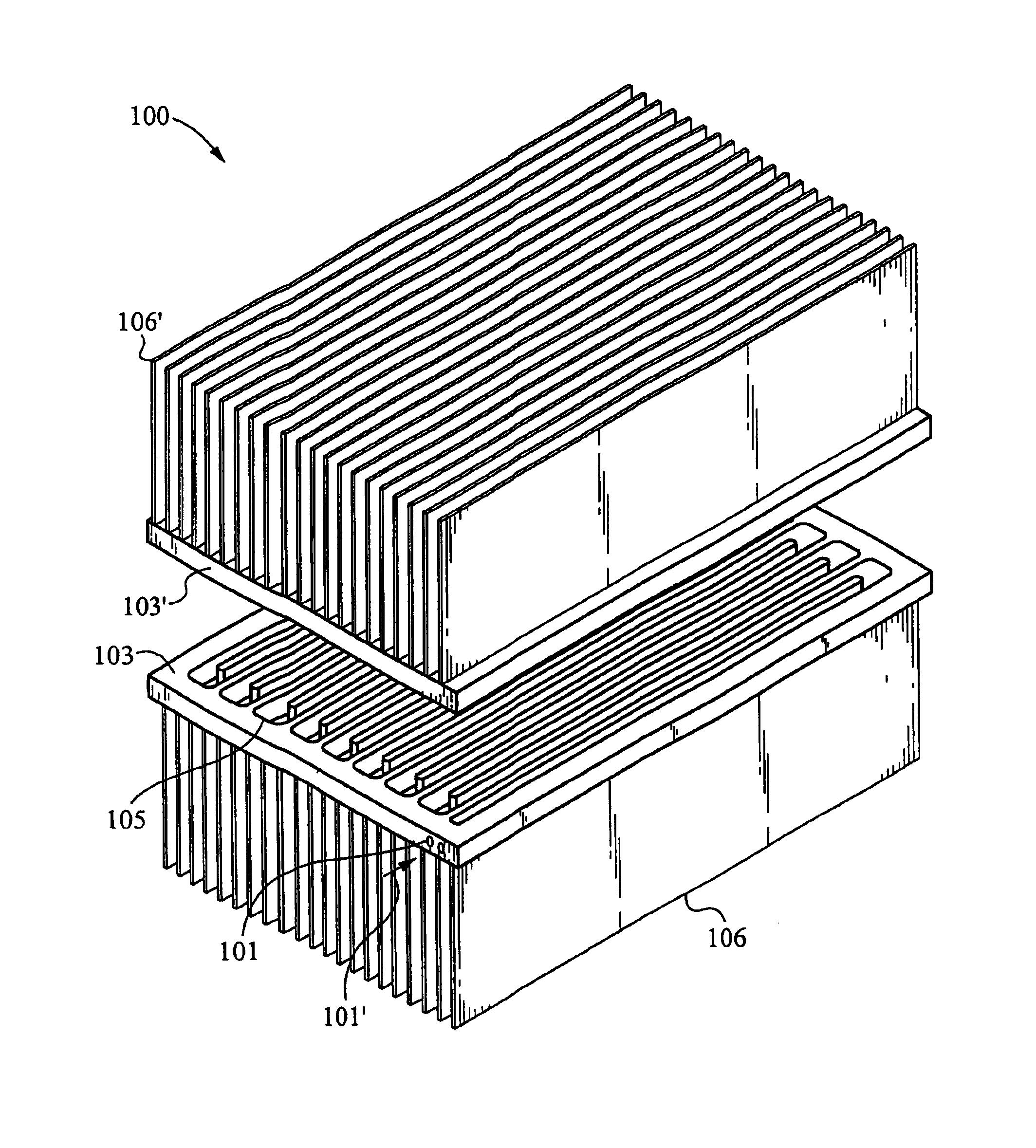
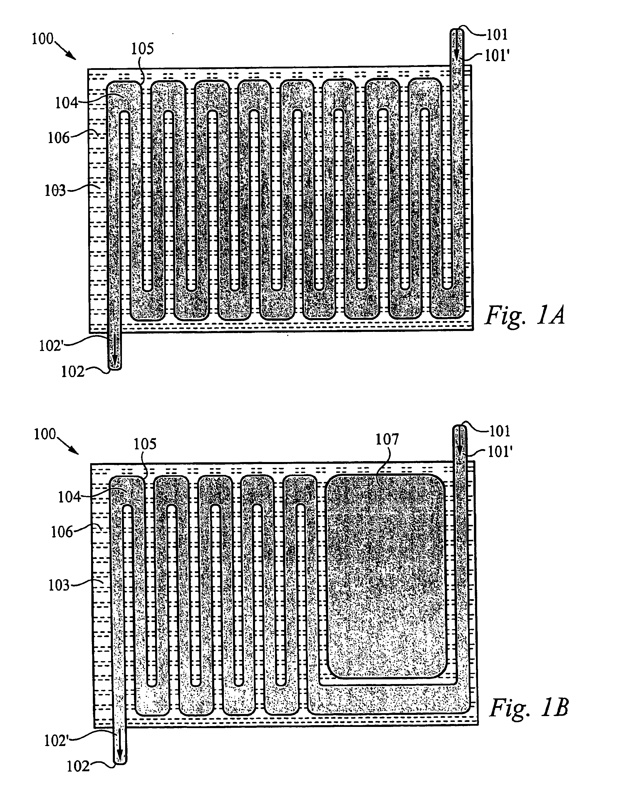
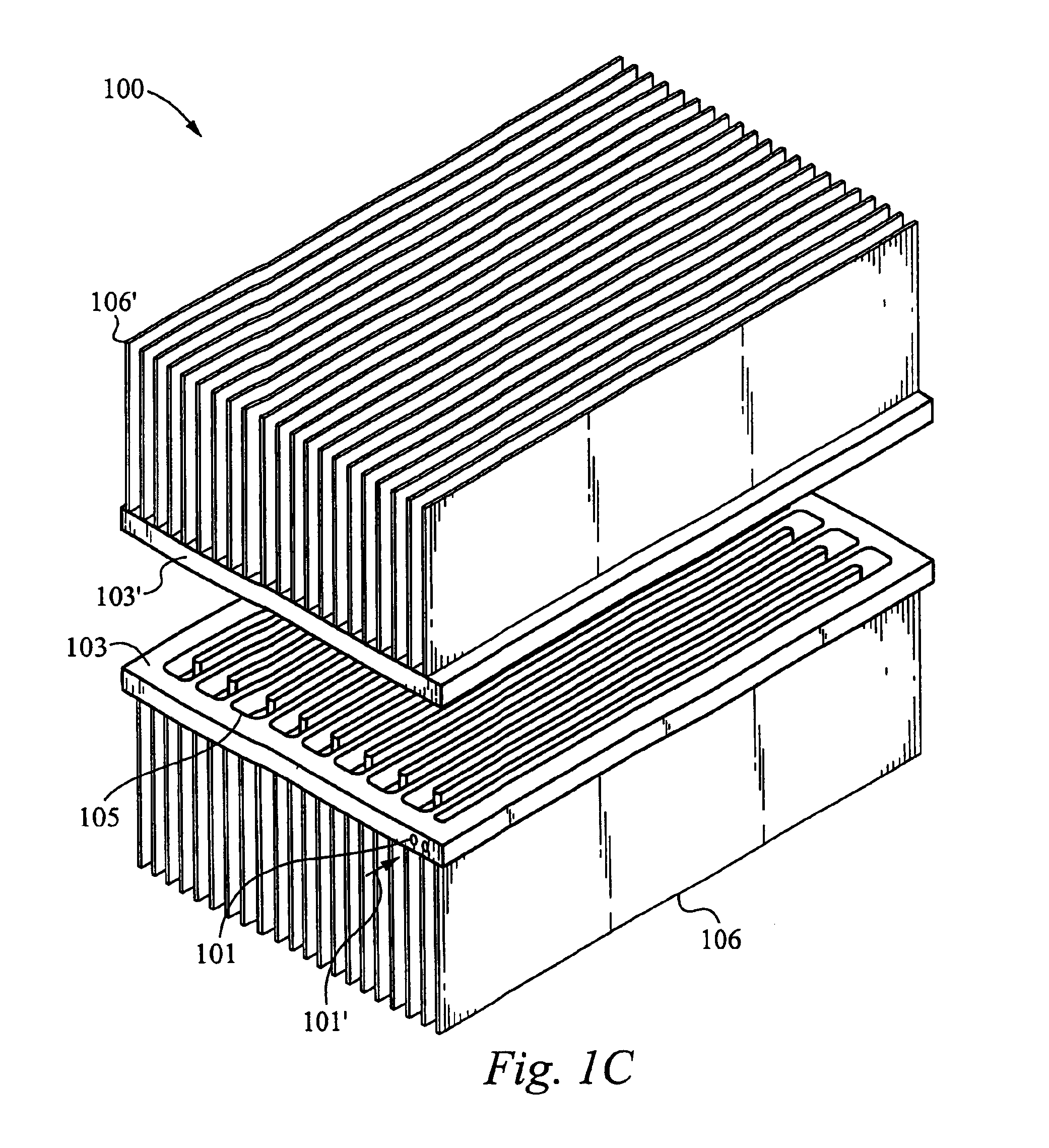
[0027]Unlike prior art, embodiments of the fluid cooled channeled flat plate fin heat exchange device disclosed in the current invention provide high heat transfer area per unit volume in an optimal manner for use in cooling heat sources including electronic components such as, but not limited to, CPU's, integrated circuits, and microprocessors. Further, the current invention optimizes temperature uniformity in the X-Y direction of the heat exchange device in addition to dissipating heat to the ambient with low thermal resistance—a shortcoming of current traditional heat dissipation methods which only transfer heat in one direction. For example, embodiments of the current invention can dissipate heat fluxes exceeding 100 W / cm2 by utilizing fluid cooled channels etched in silicon or other materials.

[0028]The channels of the preferred embodiment of the fluid cooled channeled heat exchange device comprise channels with a hydraulic diameter below 5 millimeters. In addition to the fluid ...


PUM


Abstract

A device, method, and system for a fluid cooled channeled heat exchange device is disclosed. The fluid cooled channeled heat exchange device utilizes fluid circulated through a channel heat exchanger for high heat dissipation and transfer area per unit volume. The device comprises a highly thermally conductive material, preferably with less than 200 W/m-K. The preferred channel heat exchanger comprises two coupled flat plates and a plurality of fins coupled to the flat plates. At least one of the plates preferably to receive flow of a fluid in a heated state. The fluid preferably carries heat from a heat source (such as a CPU, for example). Specifically, at least one of the plates preferably comprises a plurality of condenser channels configured to receive, to condense, and to cool the fluid in the heated state. The fluid in a cooler state is preferably carried from the device to the heat source, thereby cooling the heat source.

Description

RELATED APPLICATION[0001]This Patent Application claims priority under 35 U.S.C. 119 (e) of the now abandoned U.S. Provisional Patent Application, Ser. No. 60 / 423,009, filed Nov. 1, 2002 and entitled “METHODS FOR FLEXIBLE FLUID DELIVERY AND HOTSPOT COOLING BY MICROCHANNEL HEAT SINKS” which is hereby incorporated by reference. This Patent Application also claims priority under 35 U.S.C. 119 (e) of the now abandoned U.S. Provisional Patent Application, Ser. No. 60 / 442,383, filed Jan. 24, 2003 and entitled “OPTIMIZED PLATE FIN HEAT EXCHANGER FOR CPU COOLING” which is also hereby incorporated by reference. In addition, this Patent Application claims priority under 35 U.S.C. 119 (e) of the now abandoned U.S. Provisional Patent Application, Ser. No. 60 / 455,729, filed Mar. 17, 2003 and entitled MICROCHANNEL HEAT EXCHANGER APPARATUS WITH POROUS CONFIGURATION AND METHOD OF MANUFACTURING THEREOF”, which is hereby incorporated by reference.FIELD OF THE INVENTION[0002]This invention relates to ...

Claims


Application Information

Patent Timeline
IPC IPC(8): F28F7/00F04B17/00F04B19/00F28D15/02F28F3/02F28F3/12H01L23/473H05K7/20
CPCF04B17/00F04B19/006F28D15/0266F28F3/02F28F3/12H01L23/473H01L2924/0002F28F2210/10H01L2924/00
Inventor UPADHYA, GIRISHHERMS, RICHARDZHOU, PENGGOODSON, KENNETH
Owner VERTIV CORP
Why Eureka
Try Eureka