Method and apparatus for suppressing infrared signatures

a gas turbine engine and infrared signature technology, applied in the field of gas turbine engines, can solve the problems of inability to suppress infrared signatures, and inability to reduce the effect of infrared radiation emitted, so as to reduce the effect of reducing the infrared radiation emitted

Active Publication Date: 2006-01-24
GENERAL ELECTRIC CO
View PDF18 Cites 20 Cited by
  • Summary
  • Abstract
  • Description
  • Claims
  • Application Information

AI Technical Summary

Benefits of technology

[0005]In one aspect, the present invention includes an infrared signature suppression system for reducing infrared radiation emitted by a vehicle. The system includes an elongate duct mounted on the vehicle having a hollow interior extending along an axial centerline between an upstream end and a downstream end for transporting exhaust gas emitted by the vehicle, and a baffle positioned in the hollow interior of the duct between the upstream end and the downstream end. At least a portion of at least one of the duct and the baffle includes an emissivity coating for reducing infrared radiation emitted by the vehicle.
[0006]In another aspect, the present invention includes an aircraft propulsion system for powering an airframe during flight. The aircraft propulsion system includes an aircraft engine having an outlet, and an infrared signature suppression system mounted downstream from the aircraft engine outlet for reducing infrared radiation emitted by the engine. The infrared signature suppression system includes an elongate duct mounted downstream from the aircraft engine for transporting exhaust gas emitted by the engine outlet, wherein the duct has a hollow interior extending along a centerline between an upstream end of the duct and a downstream end of the duct. The infrared signature suppression system further includes a baffle mounted inside the hollow interior of the duct for obstructing from the downstream end line-of-sight observation of the metal engine components, and an emissivity coating applied to at least one of the duct and the baffle.

Problems solved by technology

However, such known suppression systems may have size and weight disadvantages, in addition to possible installation penalties in engine performance.
Additionally, due to associated performance penalties it may be undesirable to use infrared suppression systems when an aircraft or vehicle is operating under non-combat conditions.
However, removing infrared suppression systems from aircraft / vehicles may be difficult and time-consuming.

Method used


Image

  • Method and apparatus for suppressing infrared signatures
  • Method and apparatus for suppressing infrared signatures
  • Method and apparatus for suppressing infrared signatures

Examples


Embodiment Construction

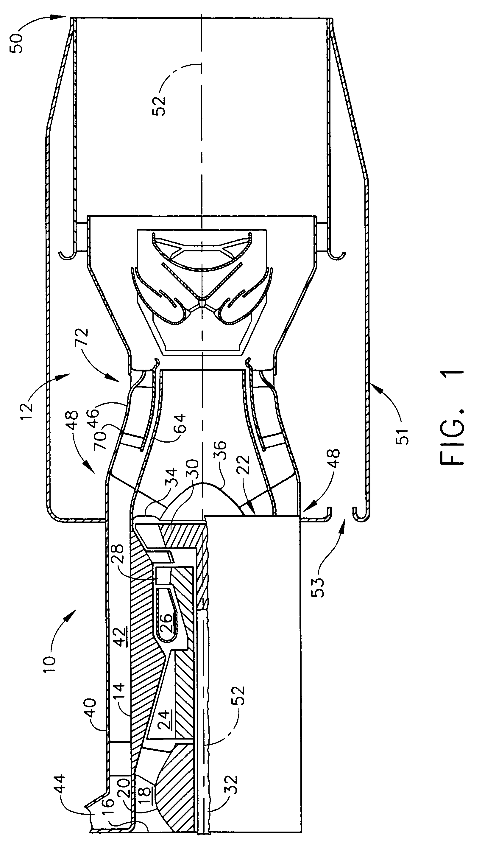
[0018]Referring now to the drawings, FIG. 1 is a cross-sectional schematic of a gas turbine engine 10 having an infrared suppression system 12 for reducing infrared radiation emitted from the engine 10. The gas turbine engine 10 includes an outer casing 14 having an open upstream end 16 to provide an airflow inlet. An annular passageway 18 defined by the outer casing 14 and an inner flowpath 20 extends axially from the upstream end 16 to a downstream end 22 of the engine 10. Air entering the upstream end 16 flows along the annular passageway 18 through a compressor 24 wherein the air is compressed. The compressed air from the compressor 24 is channeled to a combustor 26, wherein it is mixed with a fuel and ignited to produce hot combustion gases. The hot combustion gases are channeled from the combustor 26 to drive a turbine 28 that drives the compressor 24 and a low pressure turbine 30 that drives a turbine shaft 32 used to power an external mechanism, such as a helicopter rotor.

[0...


PUM

PropertyMeasurementUnit
radiusaaaaaaaaaa
radiusaaaaaaaaaa
emissivityaaaaaaaaaa

Abstract

An infrared signature suppression system for reducing infrared radiation emitted by a vehicle. The system includes an elongate duct mounted on the vehicle having a hollow interior extending along an axial centerline between an upstream end and a downstream end for transporting exhaust gas emitted by the vehicle, and a baffle positioned in the hollow interior of the duct between the upstream end and the downstream end. At least a portion of at least one of the duct and the baffle includes an emissivity coating for reducing infrared radiation emitted by the vehicle.

Description

BACKGROUND OF THE INVENTION[0001]The present invention relates generally to gas turbine engines, and more specifically to a method and apparatus for suppressing the infrared signature of a gas turbine engine.[0002]Gas turbine engines typically include a compressor, a combustor, and a turbine section. Airflow entering the compressor is compressed and channeled to the combustor, wherein air is mixed with a fuel and ignited within a combustion chamber to produce combustion gases. The combustion gases are channeled to the turbine section that extracts energy from the combustion gases for powering the compressor. The turbine section may include two independent turbines. One turbine extracts energy from the combustion gases to power the compressor. The other turbine may be used to power an output shaft connected to a load, such as a fan, an electrical generator, or a helicopter rotor. The combustion gases exiting the turbine(s) are discharged from the engine through an engine exhaust.[000...

Claims


Application Information

Patent Timeline
Patent Type & Authority Patents(United States)
IPC IPC(8): F02K3/00B64D33/04F02K1/82
CPCB64D33/04F02K1/825B64D2033/045F05D2300/502F05D2240/126F05D2230/90F05D2300/611Y02T50/671Y02T50/60
Inventor STEYER, WILLIAMKIEFFER, CHRISTOPHER MARLOWJASANY, JOHN MICHAELHOFFMAN, JACOB
Owner GENERAL ELECTRIC CO
Why Eureka
Try Eureka