

Enhanced multimode fiber
a multi-mode fiber and enhanced technology, applied in the field of enhanced multi-mode fiber, can solve the problem that the new core-core interface is not sufficiently spaced from the core-cladding interface, and achieve the effect of widening the operating bandwidth and large coarse wavelength division multiplexed channel sets
- Summary
- Abstract
- Description
- Claims
- Application Information
AI Technical Summary
Benefits of technology
Problems solved by technology
Method used
Image

Examples
examples
[0119]Examples have been selected from ongoing development work. One objective of this work is realization of a particular promise of mode mixing—that of permitted lessened value of fiber delta without the usually-associated increased loss. Achievement of the objective is shown by comparison of Examples 4-6 with Example 3. All examples measure insertion loss for a continuous wave (cw) laser-generated signal, launched into a fiber of ten meter length, by comparison of power measurements made at fiber input and output. Fibers of all Examples were produced by MCVD under the same processing conditions. All are perturbed, with perturbations induced at critical spacings to maximize mode mixing (Eq. 5).
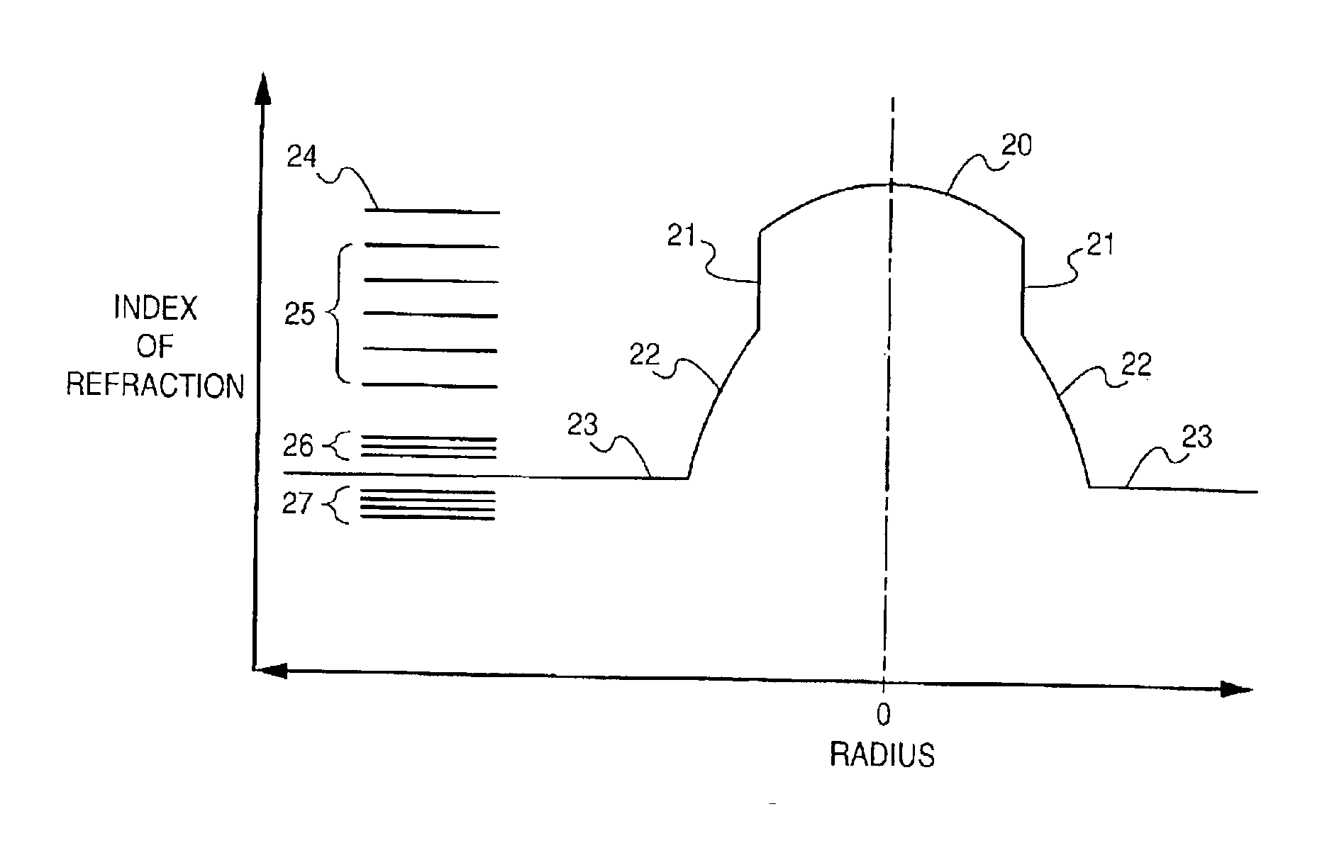
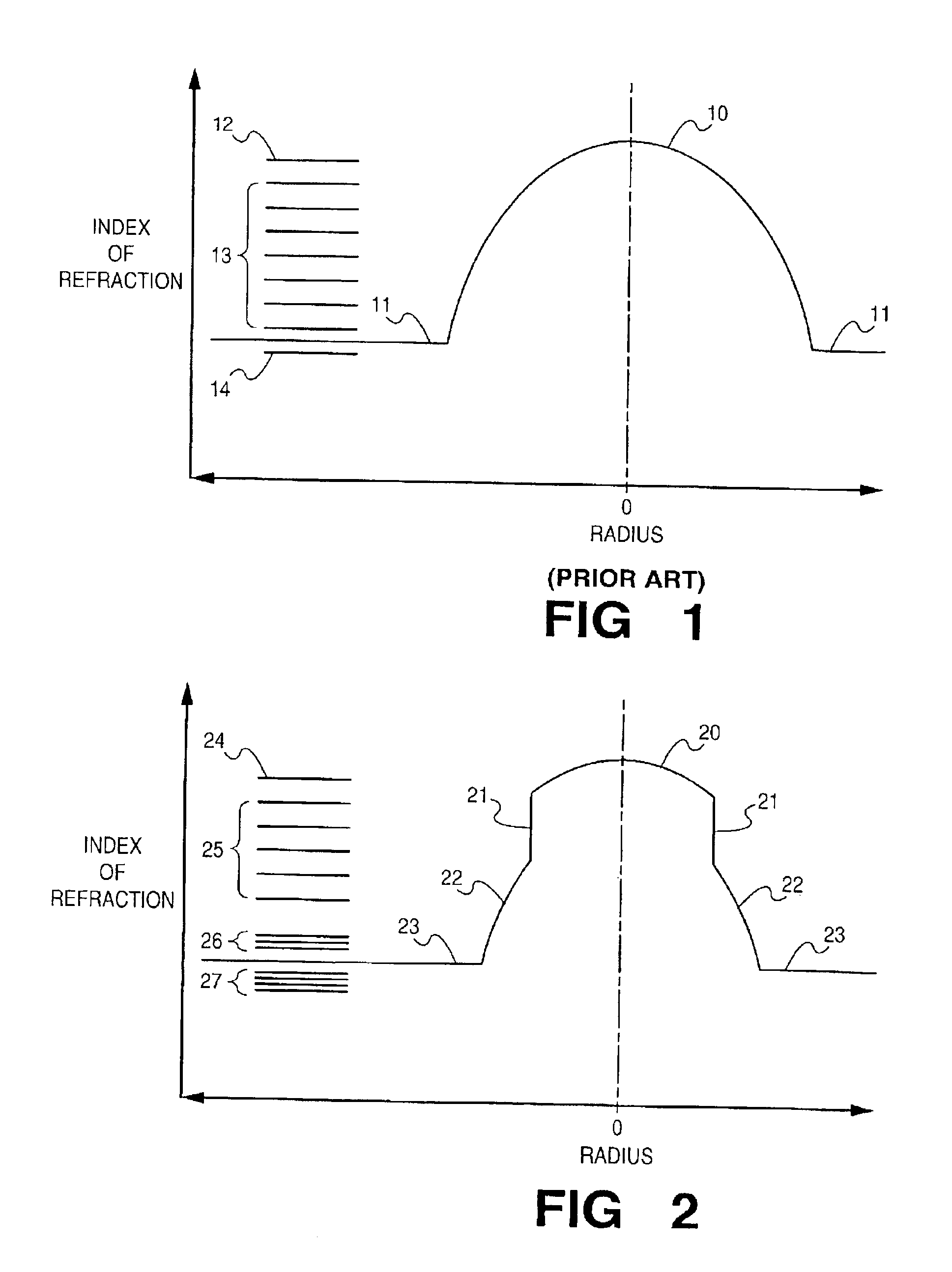
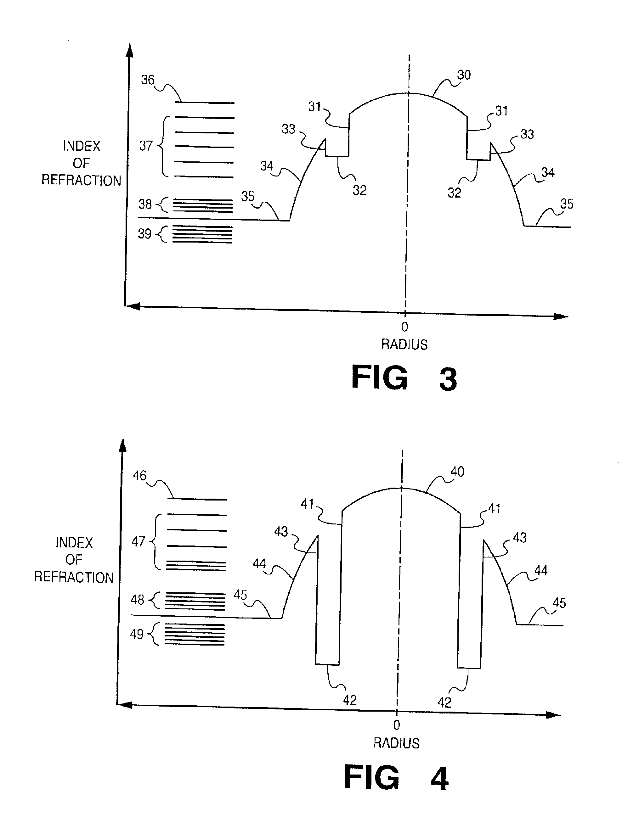
[0120]Results for Examples 1-6 are summarized on the Table. Examples 1-3 are based on three prior-art fibers of differing design, all represented by the FIG. 1 core profile. Fibers used in Examples 4-6 are of the design of Example 3, but include EMF discontinuities of the forms shown in FIGS...
example 1
[0127]A conventional, Design 1 fiber, of the profile form shown in FIG. 1, has a Δ of 2% and a core radius of 31.25 μm. At the period of maximum loss, which occurs at Λ=1000 μm, the loss for 6 pounds load is 12.4 dB. Loss is less than 0.4 dB with a 50 μm increase or decrease in the period. Measured maximum loss period correlates well with the value of 990 μm predicted by Eq. 5.
example 2
[0128]A conventional Design 2 fiber, of the profile of FIG. 1, has a delta of 1% and core radius of 25 μm. At the period of maximum loss, which occurs at Λ=1150 μm, the loss for 6 pounds load is 25 dB. Loss is less than 0.4 dB with increase or decrease of 50 μm in the period. This correlates well with the predicted location of the maximum loss at 1110 μm, from Eq. 5. The relative magnitude of the maximum loss ratio of Design 2 to Design 1 is 1.9, which is to be compared with a calculated value of 2.1.
PUM
 Abstract
Description
Claims
Application Information