Burst error pattern generation method, and burst and byte error detection correction apparatus

a technology of burst error and error pattern, applied in the direction of digital signal error detection/correction, coding, code conversion, etc., can solve the problem of high possibility of burst errors, random errors but also burst errors are frequently occurring, and burst errors are also dominant types of errors

Inactive Publication Date: 2006-01-24
FANUC LTD +1
View PDF8 Cites 25 Cited by
  • Summary
  • Abstract
  • Description
  • Claims
  • Application Information

AI Technical Summary

Problems solved by technology

In the received information stored in a continuous recording medium, such as magnetic recording or optical recording, not only random errors but also burst errors are frequently occurred.
In the information communication systems used under circumstance of susceptible influence by electromagnetic noises or cosmic particles, burst errors are also dominant type of errors.
In addition, the possibility that burst errors occur becomes much high in the signal communication in deep cosmos and the communication to / from the satellite.
But, in case that the burst error length to be corrected becomes large such as several ten bits, the number of required check bits becomes extremely large, and the quantity of circuit also becomes large.
From the practical viewpoint, therefore, this technique cannot be applied.
In such a memory, generally, as the recording surface is two-dimensional, the manufacture defects, distortion and cracks in a holographic surface, and interference between the information pieces read out from the holographic memory become two-dimensionally spread plane-like faults.
These two-dimensionally spread faults are restored on the CCD as well, as two-dimensional errors.
Therefore, there has not been a technique to decode a parallel received information, which has a large number of bits, in parallel by using a burst error detection and correction code such as the fire code.
Thus, there is a problem that parallel decoding cannot be performed.

Method used


Image

  • Burst error pattern generation method, and burst and byte error detection correction apparatus
  • Burst error pattern generation method, and burst and byte error detection correction apparatus
  • Burst error pattern generation method, and burst and byte error detection correction apparatus

Examples


Embodiment Construction

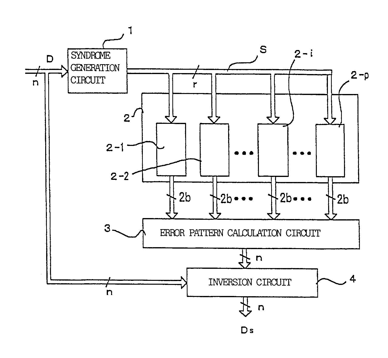
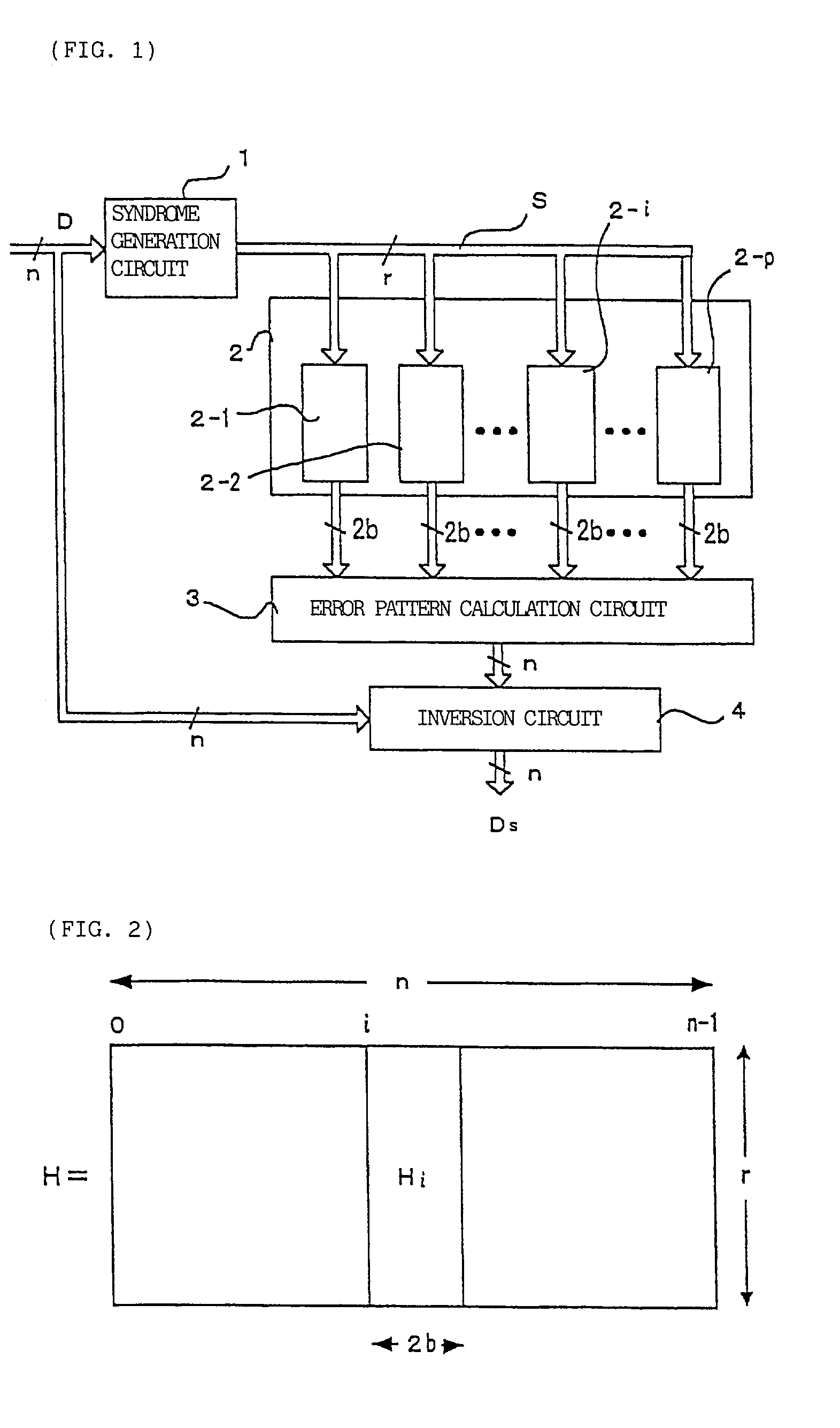
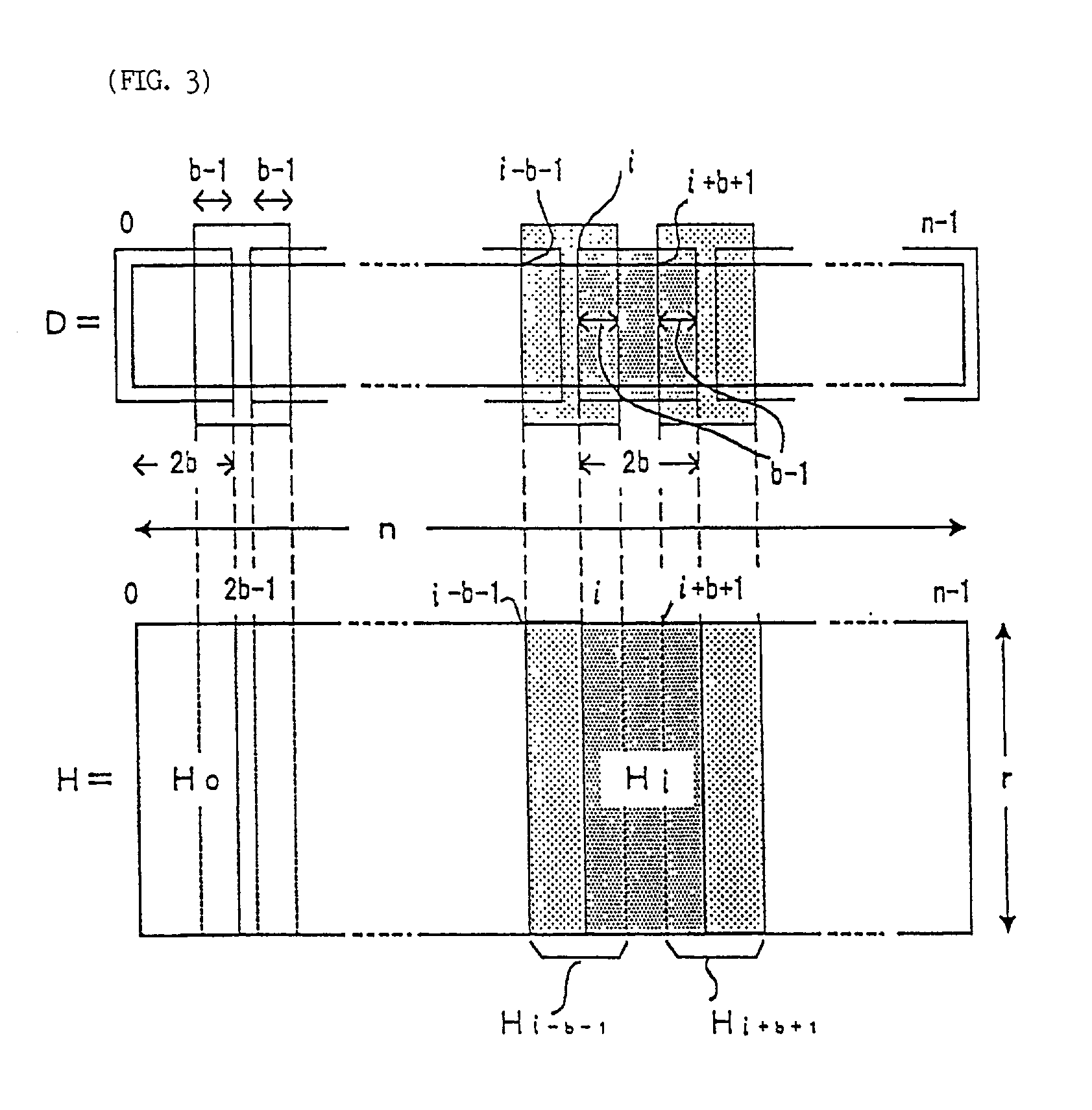
[0034]When the burst error having the length of b bits or less exists in the received information having the length of n bits, in order to correct this error, it is necessary to find the error pattern of b bits or less, and also to find the information as to the bit position with which the burst error begins in the received information. For conducting decoding in parallel, it is necessary to find the error pattern and the bit position in which the error has occurred, by forming the combinational circuit from the received n-bit information (including check bits required for burst error correction) and by conducting parallel processing. Therefore, there is demanded a technique of conducting decoding on the basis of an idea entirely different from the conventional idea.

[0035]At present, the fire code exists as a code which can detect and correct burst errors having an arbitrary length. In the present invention, however, any linear code may be used so long as it can detect and correct b...


PUM

PropertyMeasurementUnit
lengthaaaaaaaaaa
error lengthaaaaaaaaaa
light intensityaaaaaaaaaa

Abstract

A syndrome S is found from a received information D and a parity check matrix for correcting burst errors up to b bits. The syndrome S is inputted to p sets of burst error pattern generation circuits that correspond to information frames overlapping each other by (b−1) bits and each having a length of 2b bits. If a burst error is included entirely in any one of the p sets of burst error pattern generation circuits, then the burst error pattern is outputted. An error pattern calculation circuit executes OR respectively on overlapping bits output from the error pattern generation circuits. By executing exclusive OR on an output of the error pattern calculation circuit and received information D, corrected information Ds is obtained. As a result, a burst error in the received information can be detected and corrected.

Description

BACKGROUND OF THE INVENTION[0001]1. Field of the Invention[0002]The present invention relates to a pattern generation method of burst errors existing in a received information, and a detection and correction apparatus for burst errors, or for byte errors which are a special form of burst errors.[0003]2. Description of the Prior Art[0004]In the received information stored in a continuous recording medium, such as magnetic recording or optical recording, not only random errors but also burst errors are frequently occurred. In the information communication systems used under circumstance of susceptible influence by electromagnetic noises or cosmic particles, burst errors are also dominant type of errors. In addition, the possibility that burst errors occur becomes much high in the signal communication in deep cosmos and the communication to / from the satellite.[0005]Information transmission and reception are processed bit by bit in the conventional magnetic disks, optical disks and comm...

Claims


Application Information

Patent Timeline
Patent Type & Authority Patents(United States)
IPC IPC(8): H03M13/03G06F11/10G11B20/18H03M13/17H04L1/00
CPCH03M13/17
Inventor FUJIWARA, EIJIKINOSHITA, JIRO
Owner FANUC LTD
Why Eureka
Try Eureka