Injection control system of diesel engine

a technology of injection control system and diesel engine, which is applied in the direction of electric control, fuel injection pump, machine/engine, etc., can solve problems such as error and inhibiting

Active Publication Date: 2006-01-31
DENSO CORP
View PDF6 Cites 25 Cited by
  • Summary
  • Abstract
  • Description
  • Claims
  • Application Information

AI Technical Summary

Problems solved by technology

Thus, when the injection quantity is learned based on a rotation speed fluctuation caused by the single injection, influence of a fluctuation of the load of the fuel pump, which can cause an error, can be inhibited.

Method used


Image

  • Injection control system of diesel engine
  • Injection control system of diesel engine
  • Injection control system of diesel engine

Examples


first embodiment

[0019

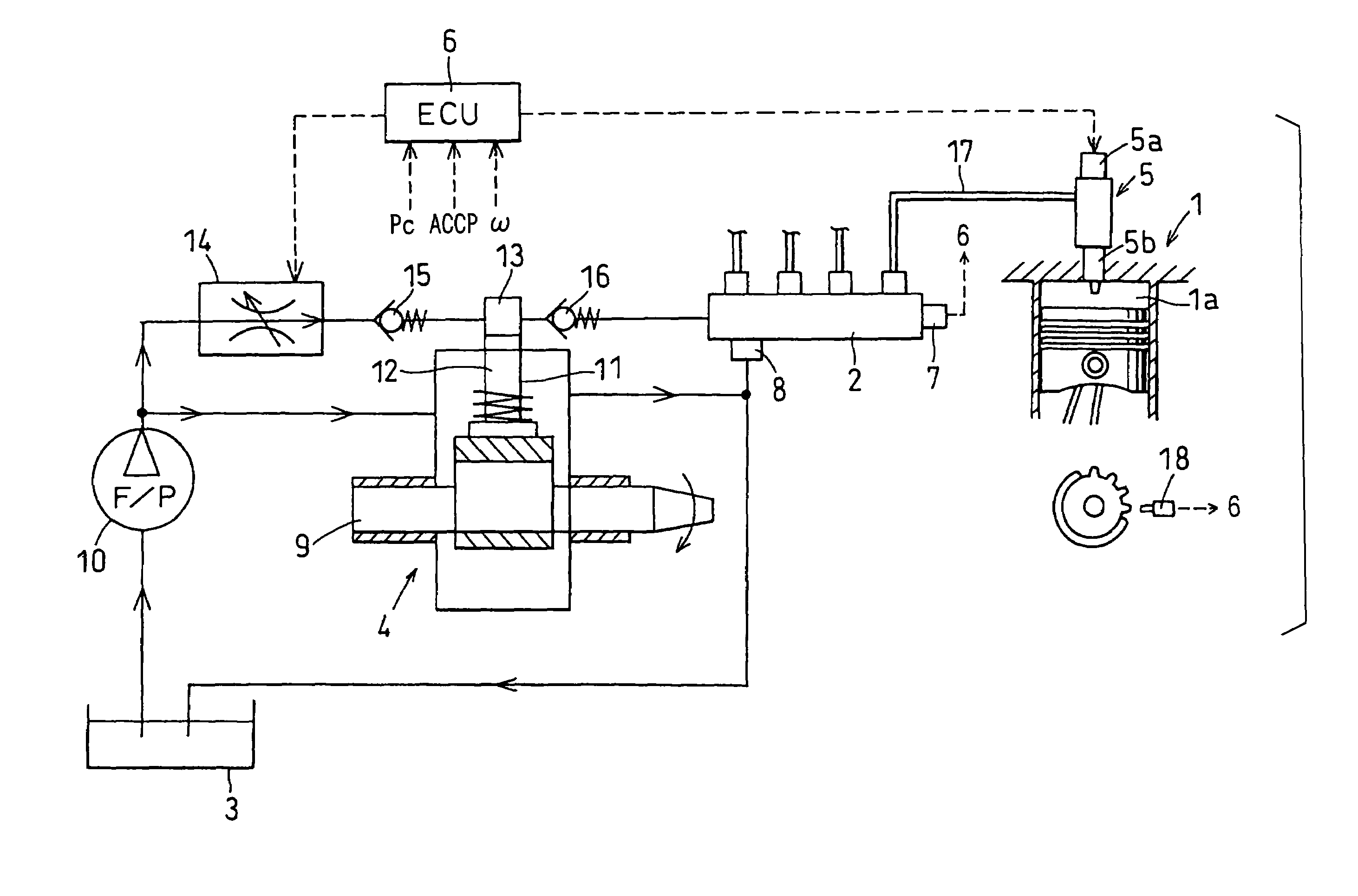
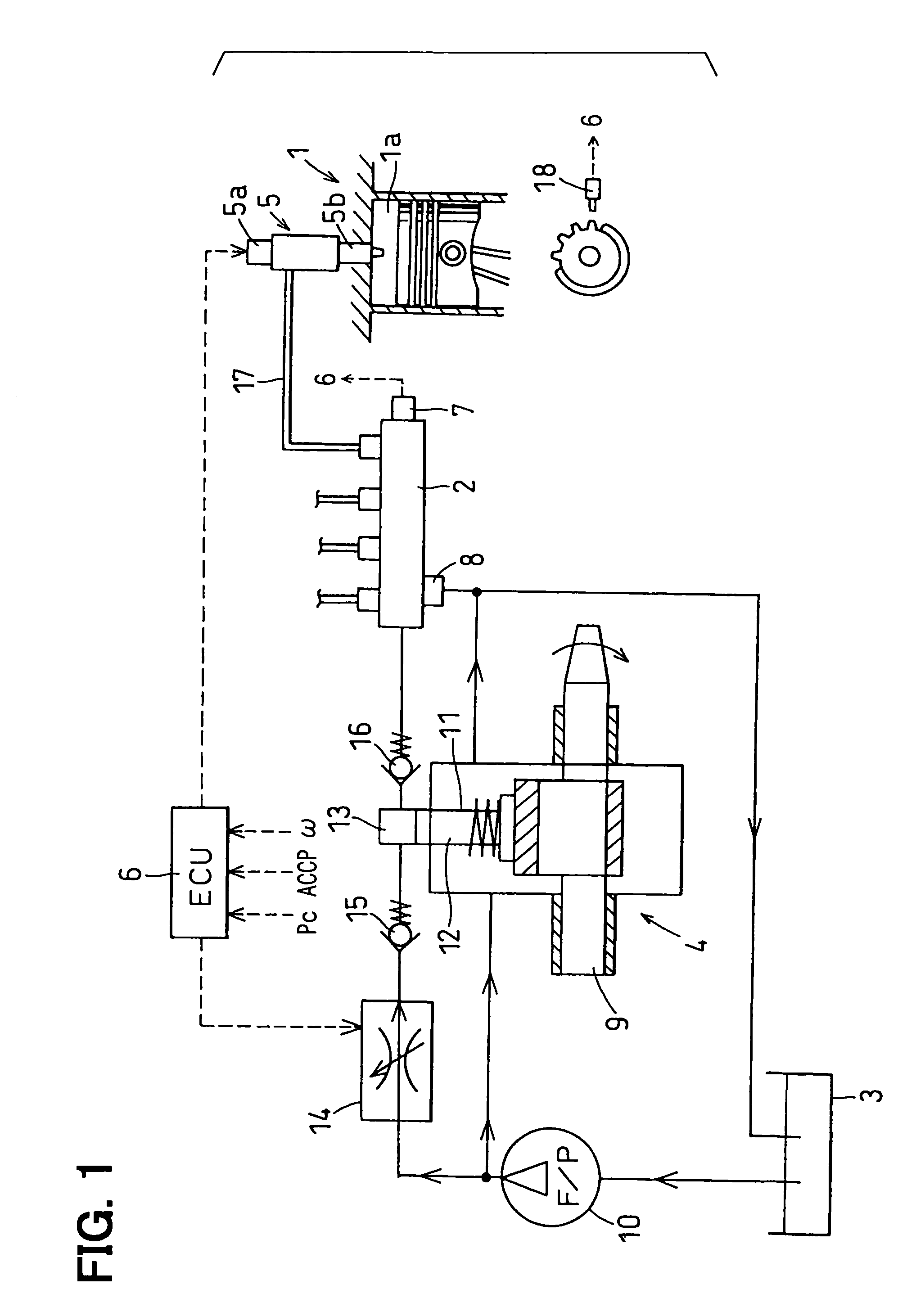
[0020]Referring to FIG. 1, a control system of a four-cylinder diesel engine 1 according to a first embodiment of the present invention is illustrated. As shown in FIG. 1, the engine 1 of the present embodiment includes an accumulation type fuel injection system and an electronic control unit (ECU) 6 for electronically controlling the fuel injection system.

[0021]As shown in FIG. 1, the fuel injection system includes a common rail 2, a fuel pump 4 and injectors 5. The common rail 2 accumulates high-pressure fuel. The fuel pump 4 pressurizes fuel drawn from a fuel tank 3 and pressure-feeds the fuel to the common rail 2. The injectors 5 supply the high-pressure fuel, which is supplied from the common rail 2, into cylinders (combustion chambers 1a) of the engine 1.

[0022]The ECU 6 sets a target value of a rail pressure Pc of the common rail 2 (a pressure of the fuel accumulated in the common rail 2). The rail pressure Pc corresponds to a fuel injection pressure. The common rail 2 ac...

second embodiment

[0058

[0059]Next, a method of calculating the rotation speed increase δ performed by an ECU 6 according to a second embodiment of the present invention will be explained.

[0060]In the second embodiment, a difference between the engine rotation speed ω increased by performing the single injection and the engine rotation speed ω′ in the case where the single injection is not performed is calculated as the rotation speed increase δ. The crank angle corresponding to the engine rotation speed ω′ is the same as the crank angle at which the engine rotation speed ω is measured. The engine rotation speed ω′ in the case where the single injection is not performed shown by a broken line “d′” in FIG. 4 can be easily estimated from the engine rotation speed ω provided before the single injection.

[0061]In this case, if the load of the fuel pump 4 is actually stabilized at the time point t11, the single injection can be performed at a time point t12 and the rotation speed increase δ can be measured ...


PUM


Abstract

An electronic control unit (ECU) of an injection control system of an internal combustion engine determines that a load of a fuel pump is stabilized when a pressure-feeding operation delay elapses since a command pressure-feeding quantity outputted to the fuel pump reaches a certain pressure-feeding quantity necessary to maintain a target injection pressure. The ECU permits a single injection when a waiting period necessary to measure rotation speeds once for each cylinder before the single injection is performed elapses since the load of the fuel pump is stabilized. Thus, the single injection timing is determined based on the time point when the command pressure-feeding quantity is stabilized, the pressure-feeding operation delay, and the waiting period. Therefore, an injection quantity learning operation can be performed highly accurately in a short period.

Description

CROSS REFERENCE TO RELATED APPLICATION[0001]This application is based on and incorporates herein by reference Japanese Patent Application No. 2003-378664 filed on Nov. 7, 2003.BACKGROUND OF THE INVENTION[0002]1. Field of the Invention[0003]The present invention relates to an injection control system of a diesel engine for performing an injection quantity learning operation.[0004]2. Description of Related Art[0005]As a method of inhibiting combustion noise or generation of nitrogen oxides in a diesel engine, a method of performing a pilot injection for injecting a very small quantity of fuel before a main injection is known. Since a command value of the pilot injection quantity is small, improvement of injection accuracy is necessary to sufficiently exert the effect of the pilot injection of inhibiting the combustion noise and the generation of the nitrogen oxides. Therefore, an injection quantity learning operation for measuring a deviation between the command injection quantity of ...

Claims


Application Information

Patent Timeline
Patent Type & Authority Patents(United States)
IPC IPC(8): F02D41/40F02D41/04F02D45/00F02D41/12F02D41/14F02D41/24F02D41/38F02M59/36F02M63/02
CPCF02D41/2438F02M63/0225F02D41/3845F02M59/34F02D41/247F02D41/1497F02D41/2441
Inventor ASANO, MASAHIROTAKEMOTO, EIJIHARAGUCHI, HIROSHI
Owner DENSO CORP
Why Eureka
Try Eureka