Cutting element

Inactive Publication Date: 2006-01-31
SMITH INT INC
View PDF28 Cites 69 Cited by
  • Summary
  • Abstract
  • Description
  • Claims
  • Application Information

AI Technical Summary

Benefits of technology

[0011]The inventive cutter allows for an increased thickness of ultra hard material in the area making contact with the earth formation and which is subject to the impact loads while at the same time providing a relatively unchanged cutter body surface area which is brazed to the bit body. In this regard, the delamination resistance of the ultra hard material layer as well as its wear resistance and fatigue strength are increased, without effecting the retention of the cutter within the bit. Moreove

Problems solved by technology

The canted end face of the cutter can be planar, curved both in a convex o

Method used


Image

  • Cutting element
  • Cutting element
  • Cutting element

Examples


Embodiment Construction

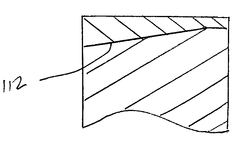
[0041]The cutting elements or cutters of the present invention have a body with a canted cutting face forming interface 112 (FIG. 5A). Stated differently, the interface is sloped. An ultra hard material layer 114 is formed over the canted interface. The upper surface 124 of the ultra hard material layer typically remains flat such that the thickness of the ultra hard material layer is minimum adjacent the highest point 128 on the interface and maximum adjacent the lowest point 126 on the canted face. Alternatively, the upper surface of the ultra hard material layer is dome-shaped (FIG. 5B). However, the radius of the dome-shaped surface is preferably relatively large such that the thickness of the ultra hard material layer is still maximum adjacent the lowest point 126 on the canted face. Preferably, the thinnest portion 133 of the ultra hard material layer should be in the order of 10–20% of the thickness of the thickest portion 134.

[0042]The overall length of the cutter of the pre...


PUM


Abstract

The present invention provides a cutting element having a cylindrical body having a canted end face on which is formed an ultra hard material layer and a method of forming the same. One or a plurality of transition layers may be provided between the ultra hard material layer and the cutting element body.

Description

CROSS-REFERENCE TO RELATED APPLICATIONS[0001]This application is a Continuation of U.S. patent application Ser. No. 09 / 693,028, filed on Oct. 20, 2000, now U.S. Pat. No. 6,405,814 which is a Divisional of U.S. patent application Ser. No. 09 / 103,824, filed on Jun. 24, 1998 now issued as U.S. Pat. No. 6,202,772.BACKGROUND OF THE INVENTION[0002]This invention relates to cutting elements for use in rock bits and more specifically to cutting elements which have a body with a canted cutting face on which is formed an ultra hard material cutting layer.[0003]A cutting element, such as a shear cutter as shown in FIG. 1, typically has a cylindrical cemented tungsten carbide body 10. The cylindrical body has a cutting face forming the interface 12. An ultra hard material layer 14 is formed over the cutting face. The ultra hard material layer is typically polycrystalline diamond or polycrystalline cubic boron nitride. The ultra hard material layer typically has a planar or dome-shaped upper sur...

Claims


Application Information

Patent Timeline
IPC IPC(8): E21B10/48E21B10/56E21B10/573
CPCE21B10/5735
Inventor EYRE, RONALD K.KESHAVAN, MADAPUSI K.TRUAX, DAVID
Owner SMITH INT INC
Why Eureka
Try Eureka