Multi-component foam dispenser with improved flow metering means

a multi-component, foam dispenser technology, applied in the direction of burners, combustion types, combustion processes, etc., can solve the problems of difficult to obtain low-flow foam components obtained using needle valves, couple together adjustment of two, and often stick of needles in the bores

Inactive Publication Date: 2006-01-31
FLEXIBLE PRODS
View PDF9 Cites 23 Cited by
  • Summary
  • Abstract
  • Description
  • Claims
  • Application Information

AI Technical Summary

Benefits of technology

[0011]Accordingly, it is a general object of the present invention to provide a foam component dispensing

Problems solved by technology

Although this action produces adequate results, it is still difficult to obtain low-flow dispensing of the foam components that might be obtained using a needle valve.
It is difficult, however, to couple together the adjustment of two needle valves on two streams of liquid/gas so that an exact ratio between the two streams is obtained.
The viscous and highly reactive nature of the foam components, particularly the isocyanate component, causes the needle to often stick in its bore, necessitating frequent disassembly and cleaning and/or replacement of the needles or even replacement of the entire dispenser.
It is also difficult to tie the two needles of the needle valve together in a manner so that movement

Method used


Image

  • Multi-component foam dispenser with improved flow metering means
  • Multi-component foam dispenser with improved flow metering means
  • Multi-component foam dispenser with improved flow metering means

Examples


Embodiment Construction

[0043]While the advantages of the invention may be achieved and practiced by the use of other structures, a preferred embodiment of the invention is of the type shown, wherein the gun assembly is made principally from plastic material and includes the various structural and functional features to be described here in detail.

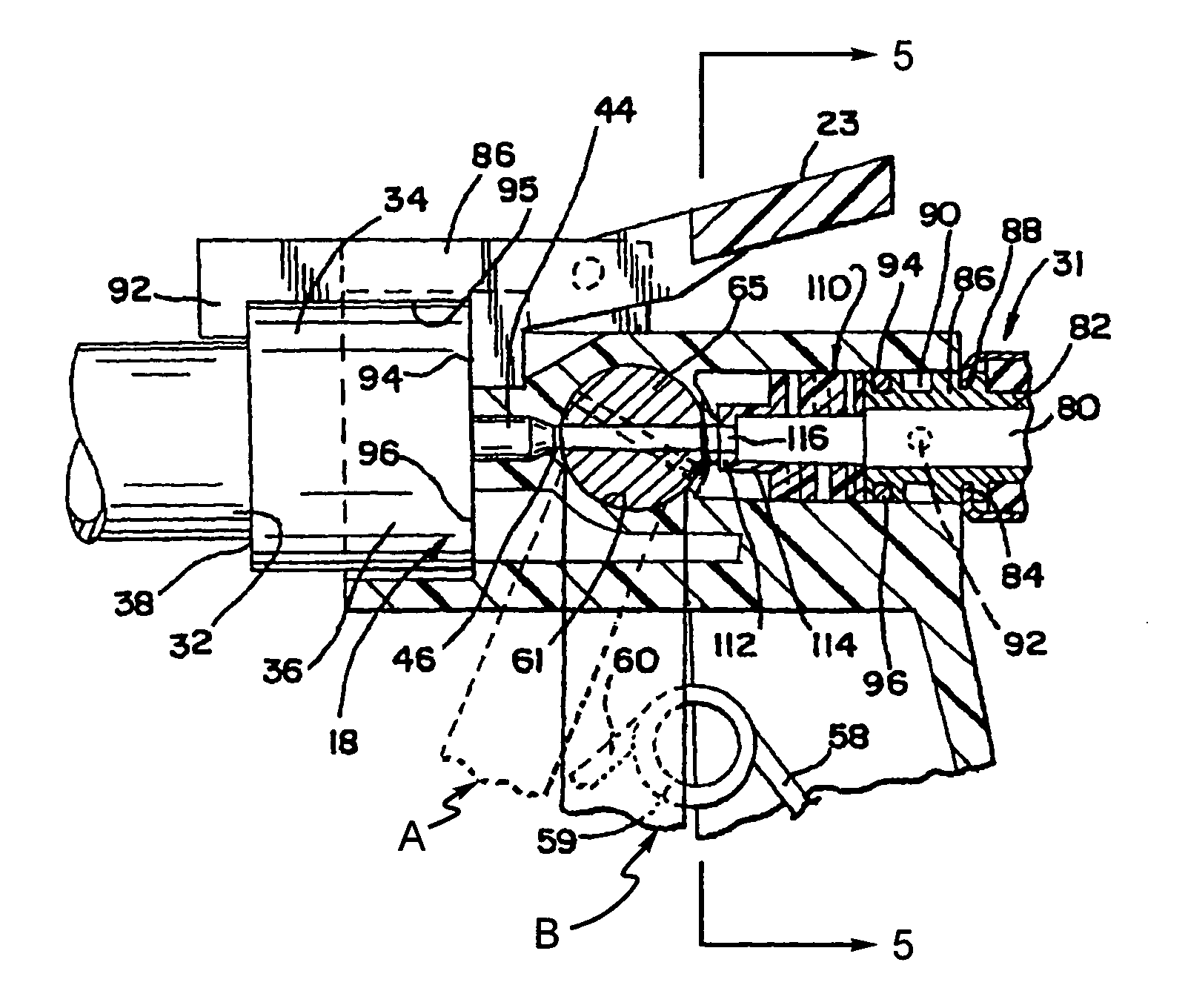
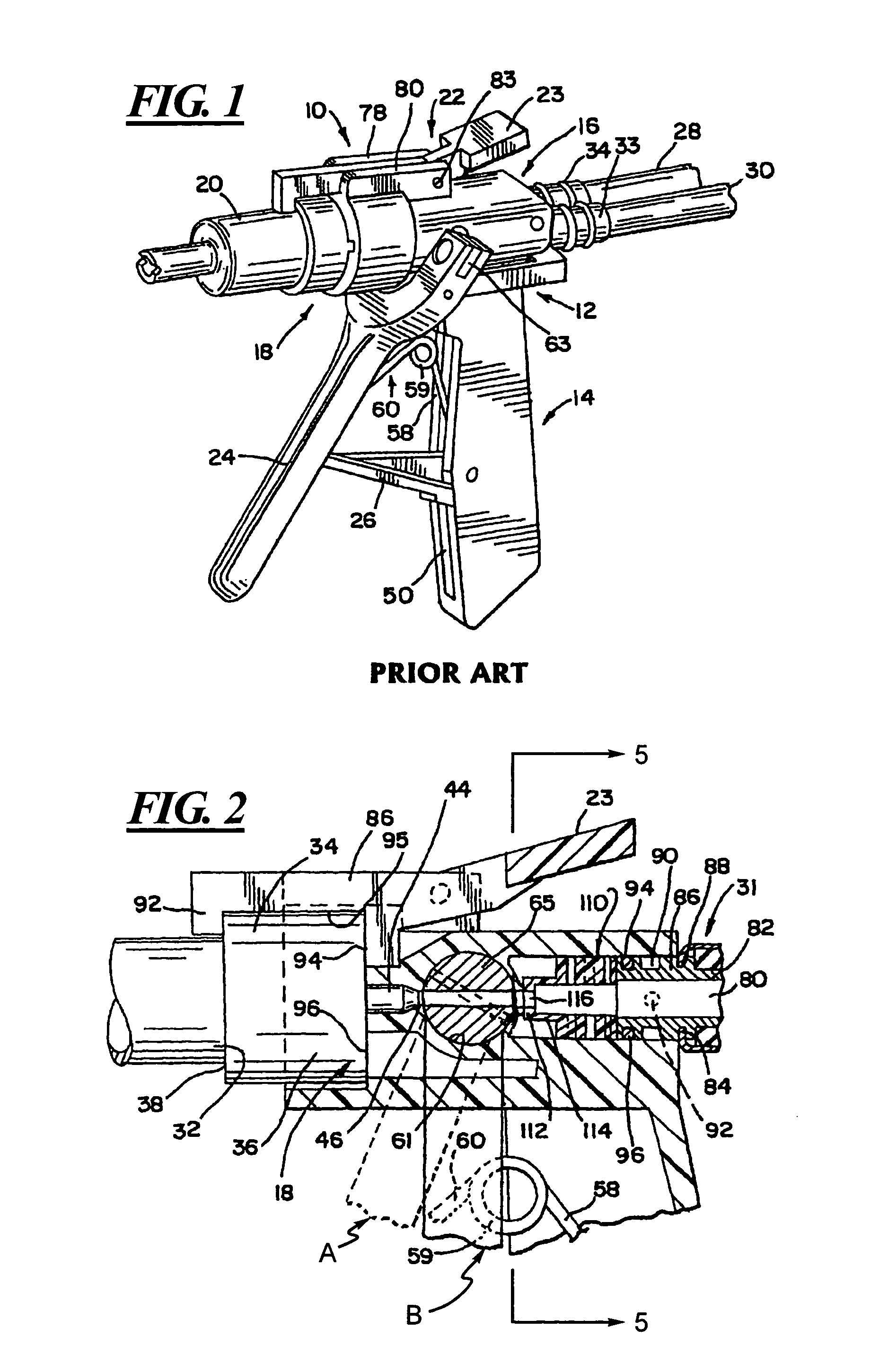
[0044]FIG. 1 illustrates generally at 10, a hand-held dispenser that is used to dispense a foam formed from two distinct foam components. The structure of this dispenser 10 is described in U.S. Pat. No. 4,676,437, issued Jun. 20, 1987, U.S. Pat No. 5,529,245, issued Jun. 25, 1996 and U.S. Pat. No. 5,944,259, issued Aug. 31, 1999, all of which are assigned to the assignee of the present invention and are incorporated herein by reference.

[0045]The gun assembly 10 is shown to include a number of principal components, including a gun body generally designated 12 and shown to be subdivided into a handle generally designated 14, a component passage and gun body flow co...


PUM

PropertyMeasurementUnit
Shapeaaaaaaaaaa
Widthaaaaaaaaaa

Abstract

An improved metering apparatus is provided for use with a foam dispenser that disperses beads of foam after mixing streams of two foam components together. The dispenser has a pair of seal passages formed in a body portion of the dispenser and a spool valve rotated mounted in the body portion. The spool valve has a pair of flow passages formed in it that can be rotated into mating alignment with the seal passages formed in the dispenser body. The spool valve flow passages have circular cross-sections while the seal passages have non-circular cross-sections, and preferably triangular cross-sections.

Description

[0001]This is a continuation of prior application Ser. No. 09 / 706,935, filed Nov. 6, 2000, which is hereby incorporated herein by reference in its entirety.BACKGROUND OF THE INVENTION[0002]The present invention relates generally to mixing and dispensing apparatus used in the polyurethane foam industry, and move particularly to a novel means for metering on ratio the flow of foam components through the dispenser.[0003]The use of urethane foams is commonplace in the building industry. Urethane foams are used as adhesives, as insulation material, as roofing components, etc. Most urethane foams used in these applications are the reaction product of two individual components, one being an “A” or isocyanate component and the other being a “B”, or resin component. These components are mixed together to typically form an expansive foam.[0004]In operation, separate containers of the A and B components are used in conjunction with a dispensing gun in which the flow of each of the A and B comp...

Claims


Application Information

Patent Timeline
IPC IPC(8): F23D11/46B05B1/02B05B1/30B05B7/04B29B7/74
CPCB29B7/7447B05B12/002B05B1/3026B05B7/0408B05B7/1209B05B12/0026
Inventor BROWN, DANIEL P.
Owner FLEXIBLE PRODS
Why Eureka
Try Eureka