High-speed stacker

a stacker and high-speed technology, applied in the direction of stacking articles, thin material handling, article delivery, etc., can solve the problems that the dual stacking arms cannot enable a fast, reliable, efficient stacker, etc., to achieve fewer timing and maintenance problems, speed up the rate at which lumber can be stacked, and improve the effect of efficiency

Inactive Publication Date: 2006-01-31
HOGUE INDS
View PDF11 Cites 6 Cited by
  • Summary
  • Abstract
  • Description
  • Claims
  • Application Information

AI Technical Summary

Benefits of technology

[0011]One objective of the present invention is to provide a stacker that is competitive in cost to build but that operates at higher speeds than conventional single or dual carriage stacker designs. According to one embodiment, the increased speed is preferably due to a simplified, positive actuating mechanism utilizing a higher degree of electronic controls. Simplified mechanical and electrical controls can result in a much faster stacking mechanism with little operation down time, lower maintenance, and less manual supervision and tuning requirements.
[0013]In some traditional lumber stackers, the courses of lumber are picked up and stacked one course at a time. According to a preferred embodiment of this invention, however, the stacking machine picks up a subsequent course of lumber while the previous course is being set. To accomplish this, a high-speed stacking machine preferably includes two sets of forks (or arms) that operate complementary to one another. This significantly speeds up the rate at which the lumber is able to be stacked.
[0014]In addition to having two sets of arms working complementary to one another, the design of one preferred embodiment utilizes a rack and pinion system, driven by a linear positioning mechanism (such as a hydraulic cylinder, drive screw linear actuator, or other linear positioning device) to horizontally move and position the stacker arms. A vertical positioning device is also preferably included to raise and lower the stacker arms to the proper vertical position at the proper speed. An electronic control system can be used to precisely monitor and control the speed and ramping of the positioning systems. Precise control of the dual stacker arms, enabled through principles of this invention, allows the stacking machine to create packages of lumber at a faster rate than previous methods and machines with fewer timing and maintenance problems.
[0015]According to yet another aspect of this invention, in addition to providing the ability to stack lumber of all sizes and mixes at higher speeds, a high-speed stacker is also preferably configured to provide the ability to disengage unnecessary stacking arms. Disengaging extra stacking arms can reduce the mass that must be moved by the positioners, and thereby permit an increase in the speed of the remaining stacking arms. This is particularly advantageous in systems where sawmill and planer mill stacker infeed production equipment are able to produce a higher piece count of shorter courses. A clutching mechanism (or any other mechanical or electrical engagement / disengagement system) could be used to disengage unneeded stacking arms from the stacking process.

Problems solved by technology

Dual stacking arms help stack faster, but without proper control, dual stacking arms cannot enable a fast, reliable, and efficient stacker.

Method used


Image

  • High-speed stacker
  • High-speed stacker
  • High-speed stacker

Examples


Embodiment Construction

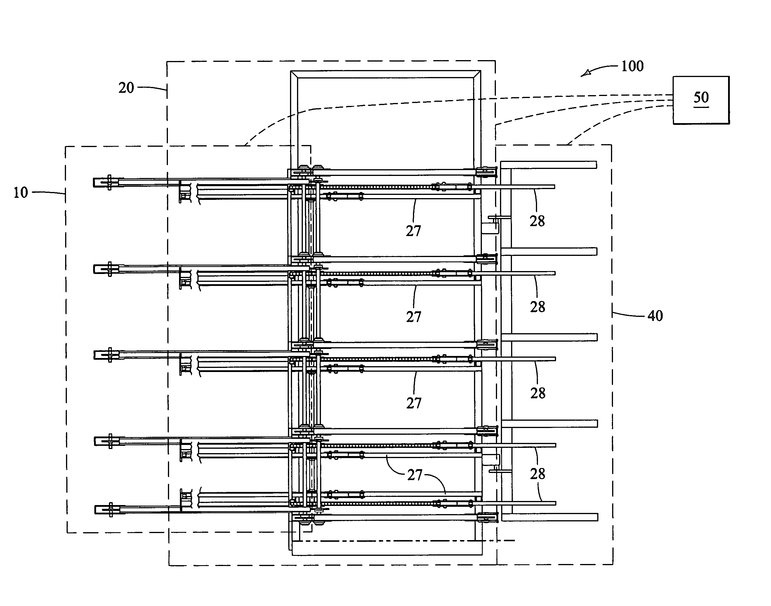
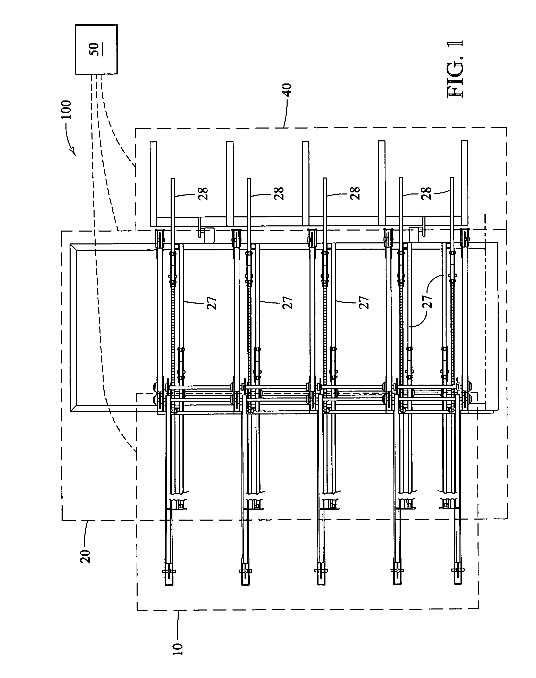
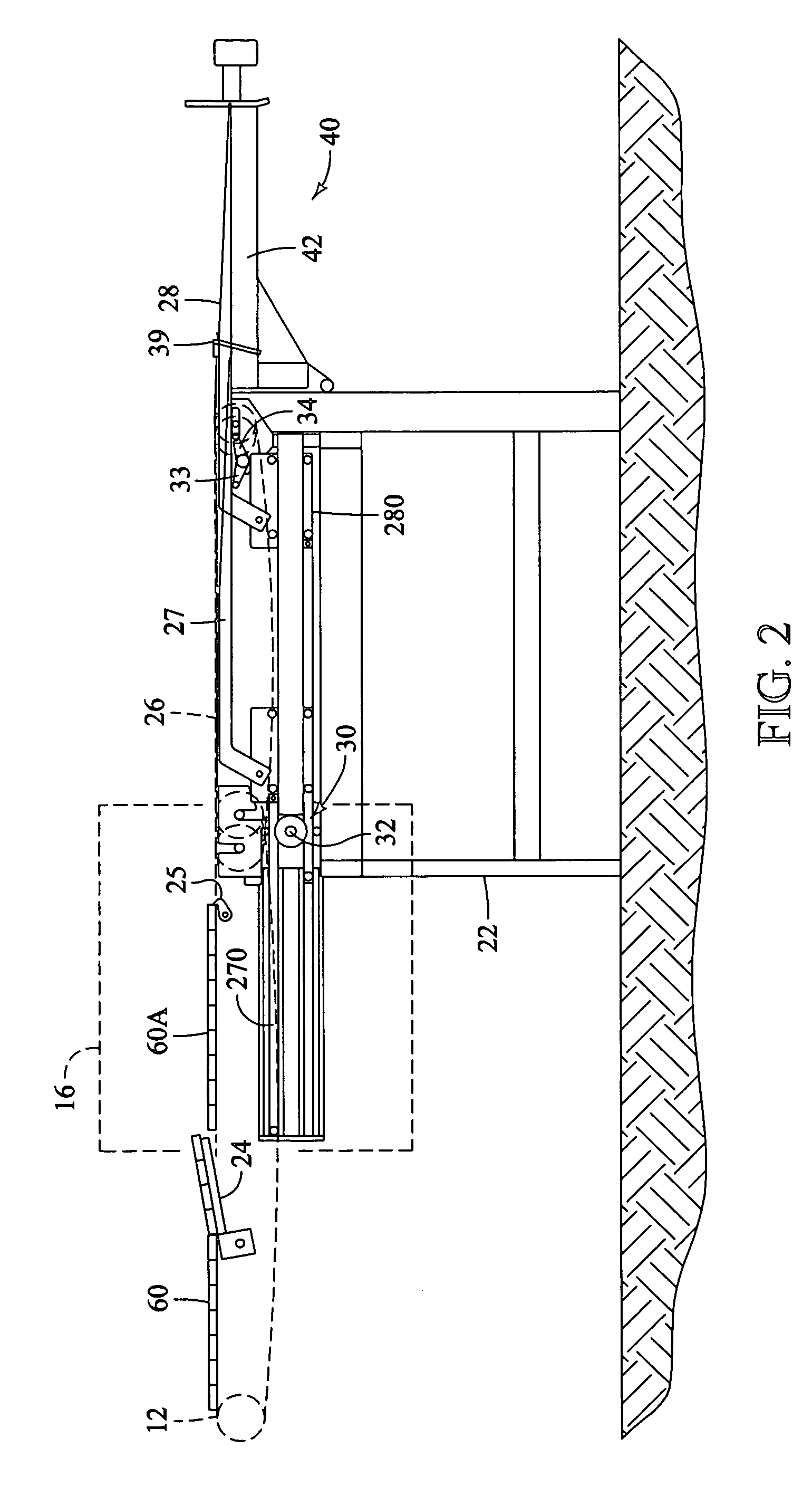
[0025]Various aspects and embodiments of the present invention will now be described in greater detail with reference to the accompany drawings. Beginning with FIGS. 1–3, a high-speed stacking system 100 according to a preferred embodiment includes a stacker infeed section 10, a dual carriage stacker 20, a package lift 40, and an electronic control system 50.

[0026]The stacker infeed section 10 preferably comprises a material conveyor 12, an even ender (not shown), and a course make-up section 16. The even ender aligns ends of the material pieces 60 with one another. The material conveyor 12 carries the material 60 (such as lumber, plywood, or other material) from a material supply to the course make-up section 16 (or pre-staging area). The material 60 can, for example, be formulated into courses 60A, using the course dividing arms 24 and course stop arms 25, in the course make-up section 16 of the stacker infeed section 10. Alternatively, however, the courses 60A can be formulated i...


PUM


Abstract

A high-speed stacker preferably includes dual stacking arms configured to operate complementary to one another. Most preferably, an electronic control system is provided to enable precise control over the speed and positioning of the stacker arms in both horizontal and vertical orientations. Linear motion devices (such as hydraulic cylinders, screw drive linear actuators, or other devices) can be used to position the arms horizontally and vertically in response to instructions from the electronic control system. In operation, the electronic control system preferably controls the speed and ramping of the stacker arms to repeatedly move courses of material from a feed system to a stacking area at a rapid rate with little maintenance. The high-speed stacker can also be configured to operate fewer than all of the stacker arms to facilitate faster stacking of smaller courses of material.

Description

[0001]This application claims priority from U.S. Provisional Application Ser. No. 60 / 520,550, filed Nov. 14, 2003, the contents of which are incorporated herein by reference in their entirety.BACKGROUND OF THE INVENTION[0002]1. Field of the Invention[0003]The present invention relates generally to methods and machines for stacking material, and more particularly, to methods and machines for stacking elongated planar members, such as sheets of lumber, plywood, or other material, into packages to facilitate subsequent shipping and / or handling.[0004]2. Description of Related Art[0005]The lumber industry, in particular, uses stacking machines (or stackers) to collect sheets (or pieces) of lumber, plywood, and other wood products into packages (or bundles) to facilitate bulk handling and shipping. Lumber is generally produced in lengths between 4′ to 28′, with thicknesses ranging from 1″ to 12″, and having widths that range between 2″ to 24″. After production, the lumber is generally gat...

Claims


Application Information

Patent Timeline
Patent Type & Authority Patents(United States)
IPC IPC(8): B65G57/18B65G57/06B65G57/10
CPCB65G57/035B65G57/06B65G57/18B65G57/10B65G2201/0282B65G2201/0217
Inventor HOGUE, GARY WAYNEHOGUE, BRIAN CORNELIUSCOLLIGAN, STEVEN M.
Owner HOGUE INDS
Why Eureka
Try Eureka