
Method and device for imaging liquid-filled container

a liquid-filled container and imaging technology, applied in the direction of counting objects on conveyors, instruments, specific gravity measurements, etc., can solve the problems of high reliability of detection errors, inability to image, absence/presence of foreign substances in liquids in containers or containers forming materials, and inability to detect the full amount of liquids in containers with high reliability, etc., to achieve the effect of improving detection precision

Inactive Publication Date: 2006-01-31
SUNTORY HLDG LTD
View PDF21 Cites 43 Cited by
  • Summary
  • Abstract
  • Description
  • Claims
  • Application Information

AI Technical Summary

Benefits of technology

[0012]With this characterizing feature, near infrared light is transmitted by the light emitting unit and this transmitted light is received by the light receiving unit for imaging the liquid-filling container. Therefore, the portion of the near infrared light travelling outside the container is received substantially directly by the light receiving unit, so that the amount of received light for the area outside the container is large. However, as may be apparent from the graph in FIG. 4, even if the container has a dark color such as black, dark green or dark brown or if the filled liquid has a dark color or even if the container has a surface frosting treatment, there occurs no significant reduction in the transmittance of the near infrared light through the liquid-filling container. So that, significant reduction in the received light amount for the area corresponding to the liquid-filling container may be avoided advantageously.
[0029]With this characterizing feature, the method or the apparatus according to the present invention detects any foreign substance present in the container or in a material forming the container. Then, the detection for the area corresponding to this container of the foreign substance mixed in the container material is made possible. As a result, the detection of the foreign substance mixed in the container material can be effected reliably, regardless of the color of the container or the color of the liquid or regardless of presence / absence of bubbles near the liquid surface.

Problems solved by technology

However, the imaging becomes difficult in case the container is a colored container especially of a dark color such as black, dark green or dark brown or the container has a frosted surface treatment, so that the filled amount of the liquid in the container or absence / presence of any foreign substance in the liquid or in the container or container forming material cannot be detected with high reliability.
Then, since the inspection of the liquid surface of the liquid filled in the container or of the absence / presence of any foreign substance in the liquid or in the container or the container material is to be effected for such area of extremely limited received light amount, the detection error becomes significant or the detection of the liquid surface or mixed foreign substance per se becomes very difficult.
With this method, however, there remains a significant problem in the detection precision.
Further, even if the container per se does not have such dark color as black, dark green or dark brown, if the liquid filled therein has a dark color, then, the detection of foreign substance in the liquid becomes impossible.
Moreover, if fine bubbles generated in association with the filling operation of the liquid are present near the liquid surface, the amount of light transmitted through the bubbles will be small due to the effect of diffused reflection of the light by the bubbles and also the amount of light transmitted through the liquid portion will be limited, so that discrimination therebetween is difficult, thus impeding reliable detection of the liquid surface.
Also, if the foreign substance is present near the bubbles, the detection of this mixed substance too can become impossible.

Method used


Image

  • Method and device for imaging liquid-filled container
  • Method and device for imaging liquid-filled container
  • Method and device for imaging liquid-filled container

Examples


first embodiment

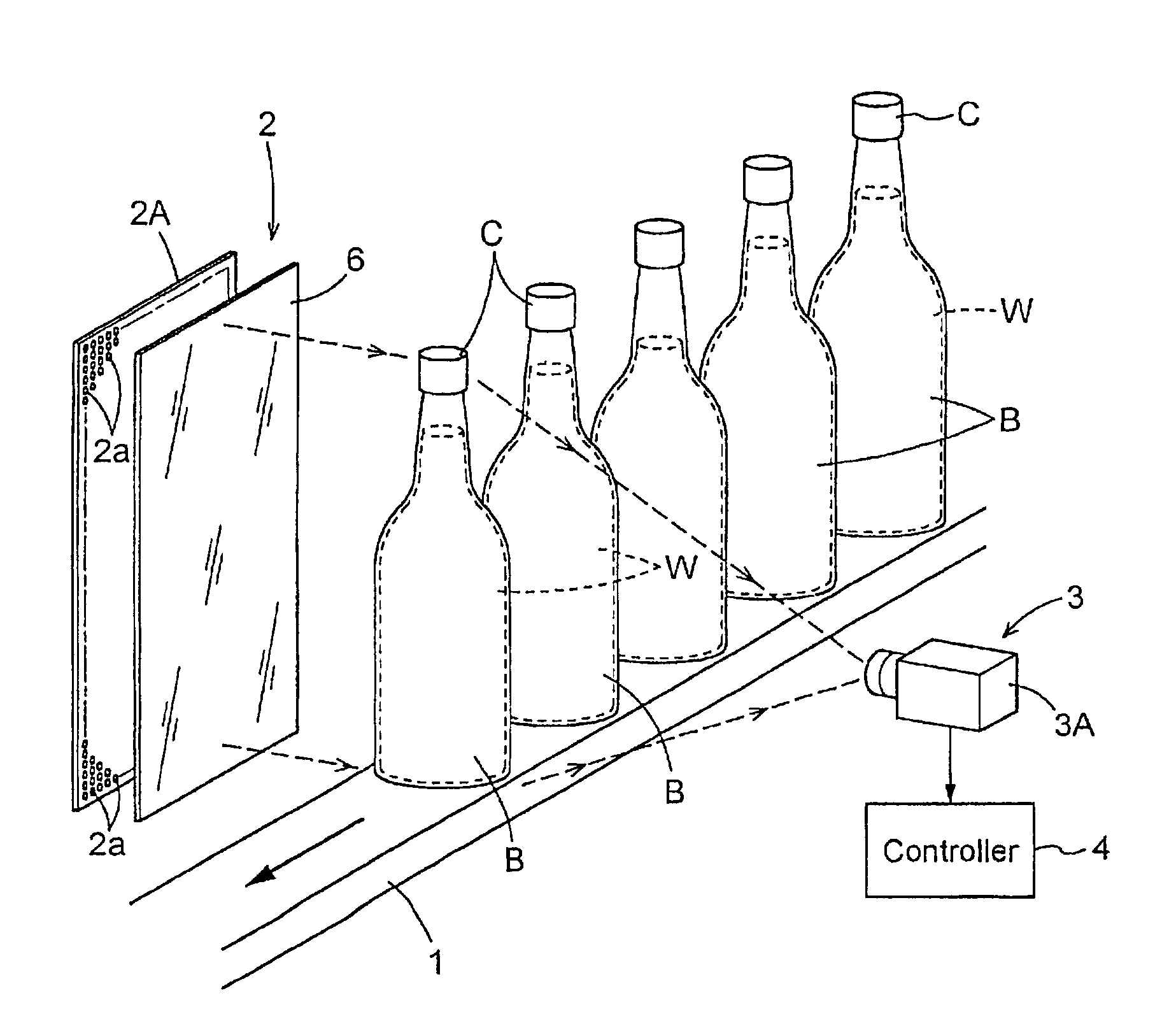
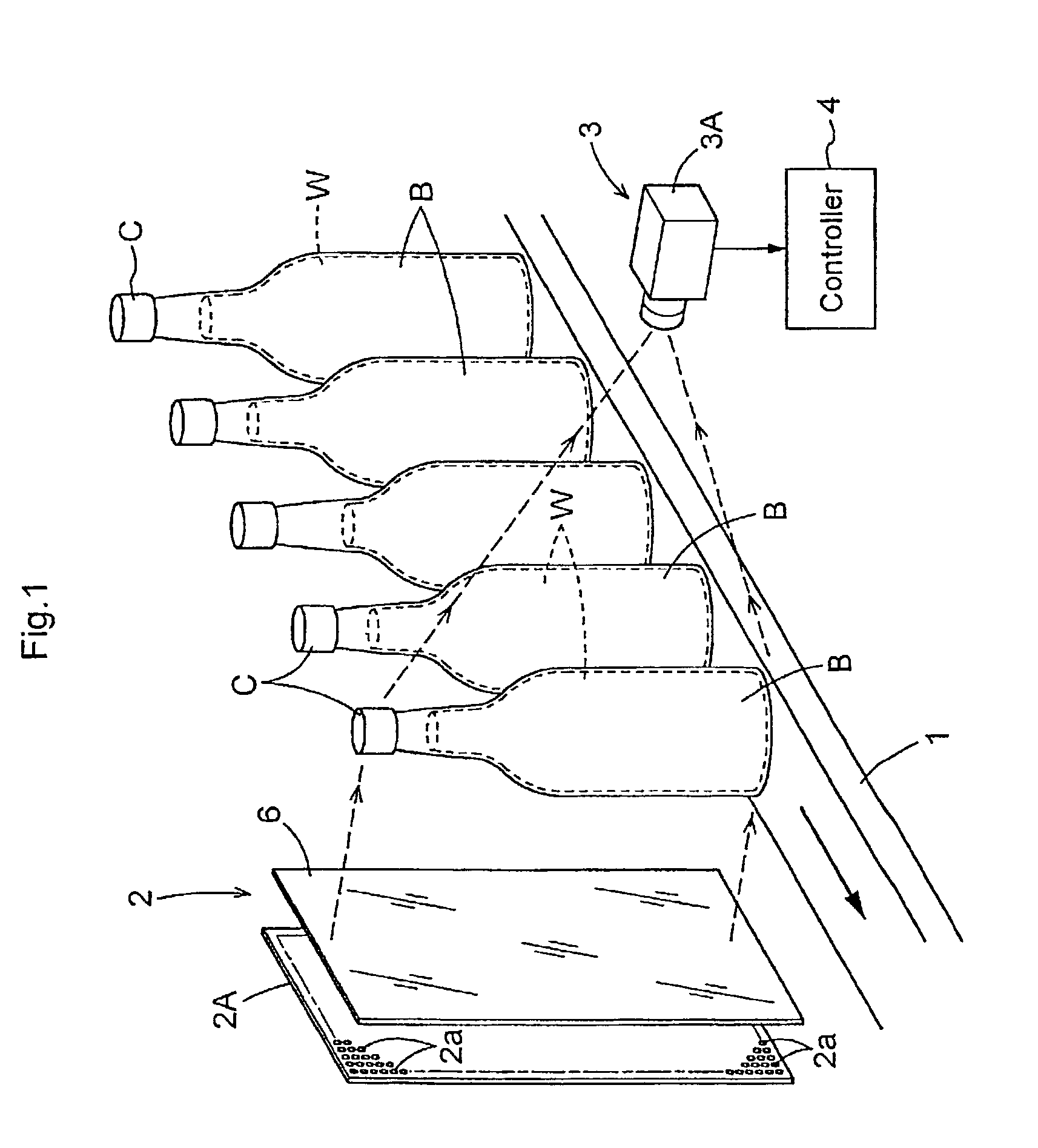
[0039]According to the invention, as shown in FIG. 1, the light emitting unit 2 comprises a light emitter 2A and on the front side of this light emitter 2A there may be provided a diffuser plate 6 formed of an acrylic plate having a milky-white color.

[0040]The light emitter 2A may comprise e.g. a plurality of LED 2a arranged in a plate-like form. These plurality of LED 2a emit a light of a predetermined wavelength ranging from 700 nm to 900 nm, preferably from 750 nm to 850 nm, as a near infrared light onto the liquid-filing container B being conveyed on the transport conveyer 1. This irradiated light maybe a light which consists entirely of light component having the wavelength range of 700 nm to 900 nm, preferably 750 nm to 850 nm or which contains such light component as a portion thereof.

[0041]The light receiving unit 3 may comprise e.g., a light receiver 3A constituted from a CCD camera. This light receiver 3A is adapted for receiving the near infrared light emitted and irradia...

second embodiment

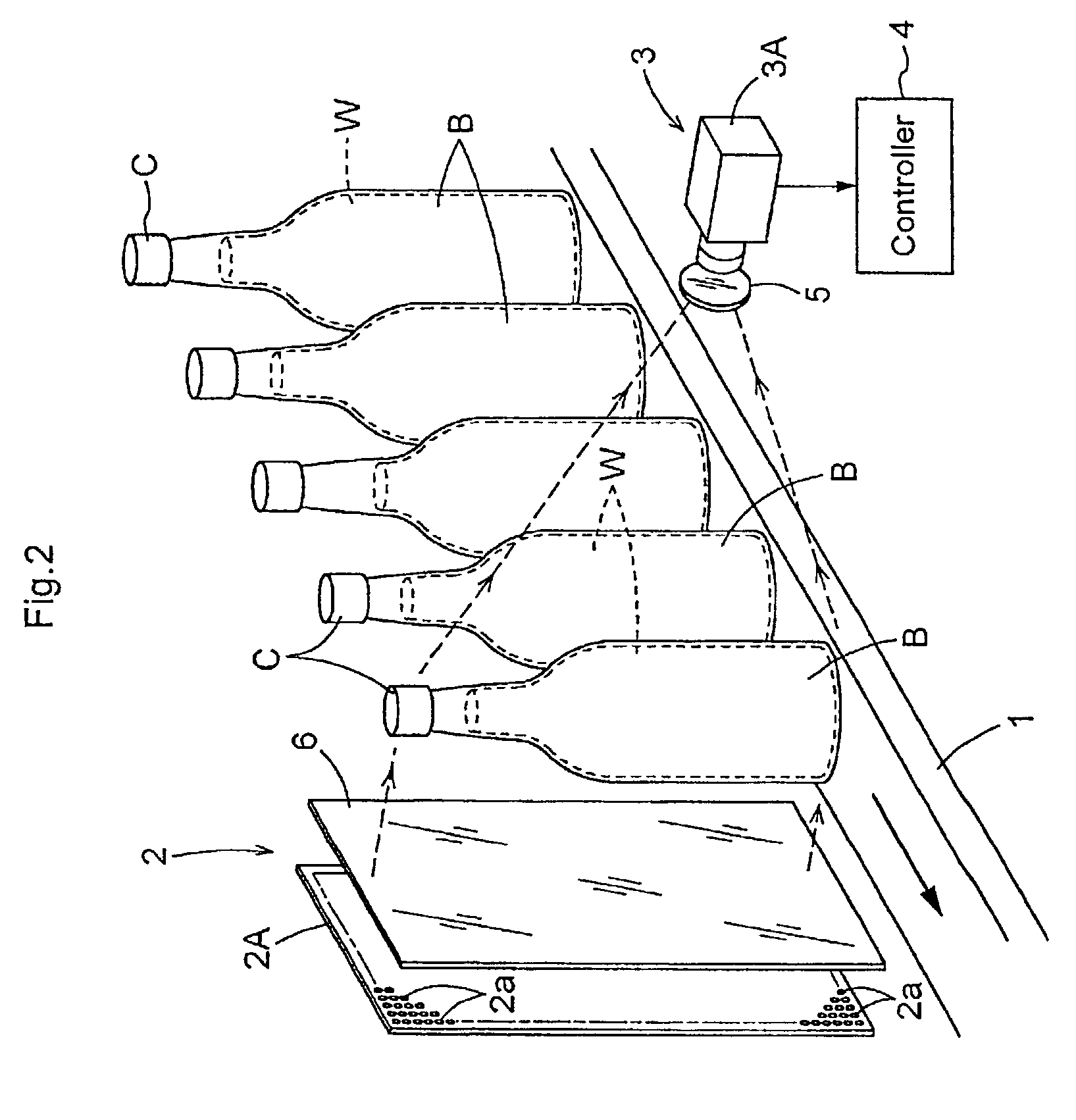
[0046]According to the present invention, as shown in FIG. 2, the light receiving unit 3 includes not only the light receiver 3A comprised of a CCD camera or the like, but also a light-receiver cut filter 5 disposed on the front side of the light receiver 3A.

[0047]On the other hand, the light emitting device 2, like the first embodiment described hereinbefore, includes the light emitter 2A comprised of a plurality of LED 2a arranged in a plate-like form and may also include, if necessary, the diffuser plate 6 made of a milky-white acrylic plate. And, the light beam emitted from the number of LED 2a is irradiated onto each liquid-filling container B as being conveyed on the transport conveyer 1.

[0048]In the above, after the light is transmitted through each liquid-filling container B, this transmitted light is first filtered by the cut filter 5, so that only or mainly its near infrared component having the wavelength ranging between 700 nm and 900 nm, preferably between 750 nm and 85...


PUM

PropertyMeasurementUnit
wavelengthaaaaaaaaaa
thicknessaaaaaaaaaa

Abstract

The present invention is a method and an apparatus for imaging a liquid-filling container in which a light emitting unit is provided for emitting and irradiating light onto the container and a light receiving unit is provided for receiving the light transmitted through the container. The object of the present invention is to provide such a method and an apparatus for imaging a liquid-filling container. This method and apparatus assures reliable detection of the surface of liquid filled in a container or of foreign substance mixed in the liquid or present in the container or the container material not only when the container is transparent, but also when the container is a colored container of a dark color such as black, dark green or dark brown or the container has a frosted surface of when the liquid filled in the container has a dark color. For accomplishing this object, according to the present invention, the light emitting unit emits near infrared light or the light receiving unit receives near infrared light for imaging the container.

Description

BACKGROUND OF THE INVENTION[0001]1. Field of the Invention[0002]The present invention relates to a method of imaging a liquid-filling container comprising the steps of emitting and irradiating light onto the container by a light emitting unit, receiving the light transmitted through the container by a light receiving unit and imaging the container based on information about the transmitted light. The invention relates also to an apparatus for carrying out the method above, including the light emitting unit and the light receiving unit.[0003]2. Description of the Prior Art[0004]The imaging of a liquid-filling container noted above is employed in a manufacturing line of various beverages such as soft drinks or alcoholic beverages in order to inspect whether the amount of liquid as the beverage filled in a container made of glass or PET is within a predetermined range or not and / or whether any foreign substance is inadvertently mixed in the beverage filled in the container or is presen...

Claims


Application Information

Patent Timeline
Patent Type & Authority Patents(United States)
IPC IPC(8): G06K9/00G01F23/292G01N21/90
CPCG01F23/292G01N21/909G01N21/9027
Inventor YAMAGISHI, TAKAHIROTAMURA, SHIGEKI
Owner SUNTORY HLDG LTD
Learn More