Floating low density concrete barrier

a concrete barrier and low density technology, applied in special-purpose vessels, water cleaning, vessel construction, etc., can solve the problems of high cost, time-consuming fabrication process, and high cost of construction, and achieve the effect of low cos

Inactive Publication Date: 2006-02-07
THE UNITED STATES OF AMERICA AS REPRESENTED BY THE SECRETARY OF THE NAVY
View PDF2 Cites 20 Cited by
  • Summary
  • Abstract
  • Description
  • Claims
  • Application Information

AI Technical Summary

Benefits of technology

[0019]Accordingly, the present invention provides a barrier for small boats. A plurality of flotation modules is cast from a buoyant concrete mixture of cement, water, beaded forms of expanded polystyrene, and polypropylene fibers that is non-water-absorbing, crushable, when compressed or impacted, causes local crushing not shear, and has a density lighter than water. One buoyant concrete mixture includes (weight=1562.5 pounds, volume=59.9 cubic feet, density=26.1 pounds per cubic foot) 1004 pounds of cement, 552 pounds of water, and 7 pounds of polypropylene fibers per volume of 48 cubic feet of polystyrene beads. The cement and water are mixed, then foam and beads at approximately 12 cubic feet of foam to 1.5 pounds of fiber are mixed into the cement/w

Problems solved by technology

Marine facilities including ships are vulnerable to sabotage by explosive laden small boats.
This ponderous pipe structure requires a time consuming fabrication procedure at a distant heavy construction site and a significant and further time consuming logistical effort to get it to the water and launched.
While these cylinders may be easier to deploy on the surface of the water than the hollow water pipe structures, their fabrication can be labor and tim

Method used


Image

  • Floating low density concrete barrier
  • Floating low density concrete barrier
  • Floating low density concrete barrier

Examples


Embodiment Construction

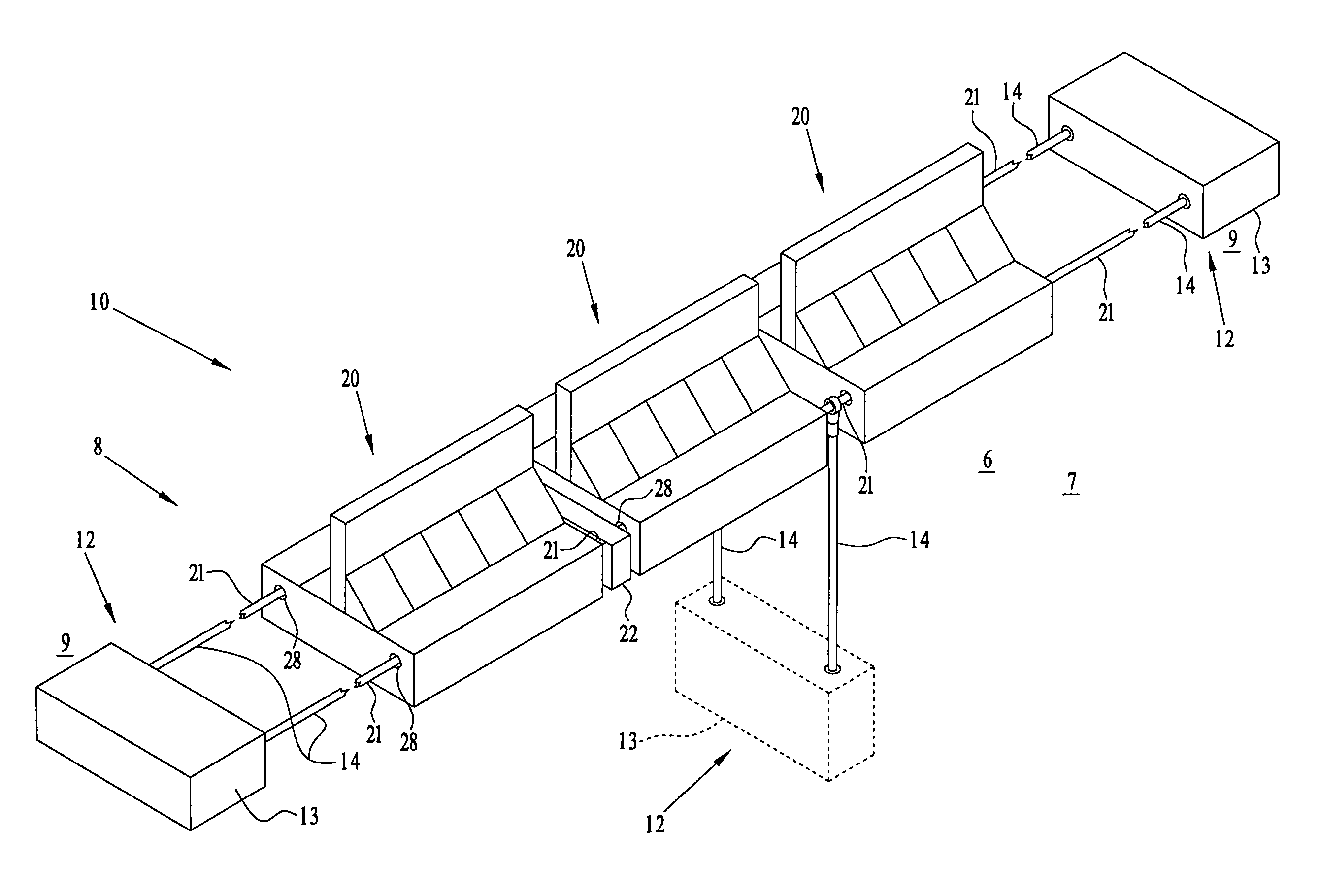
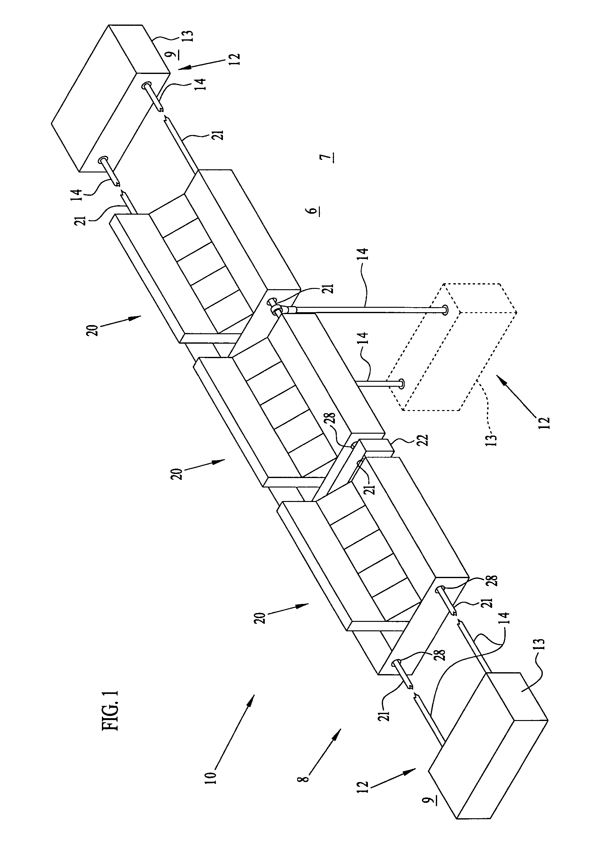
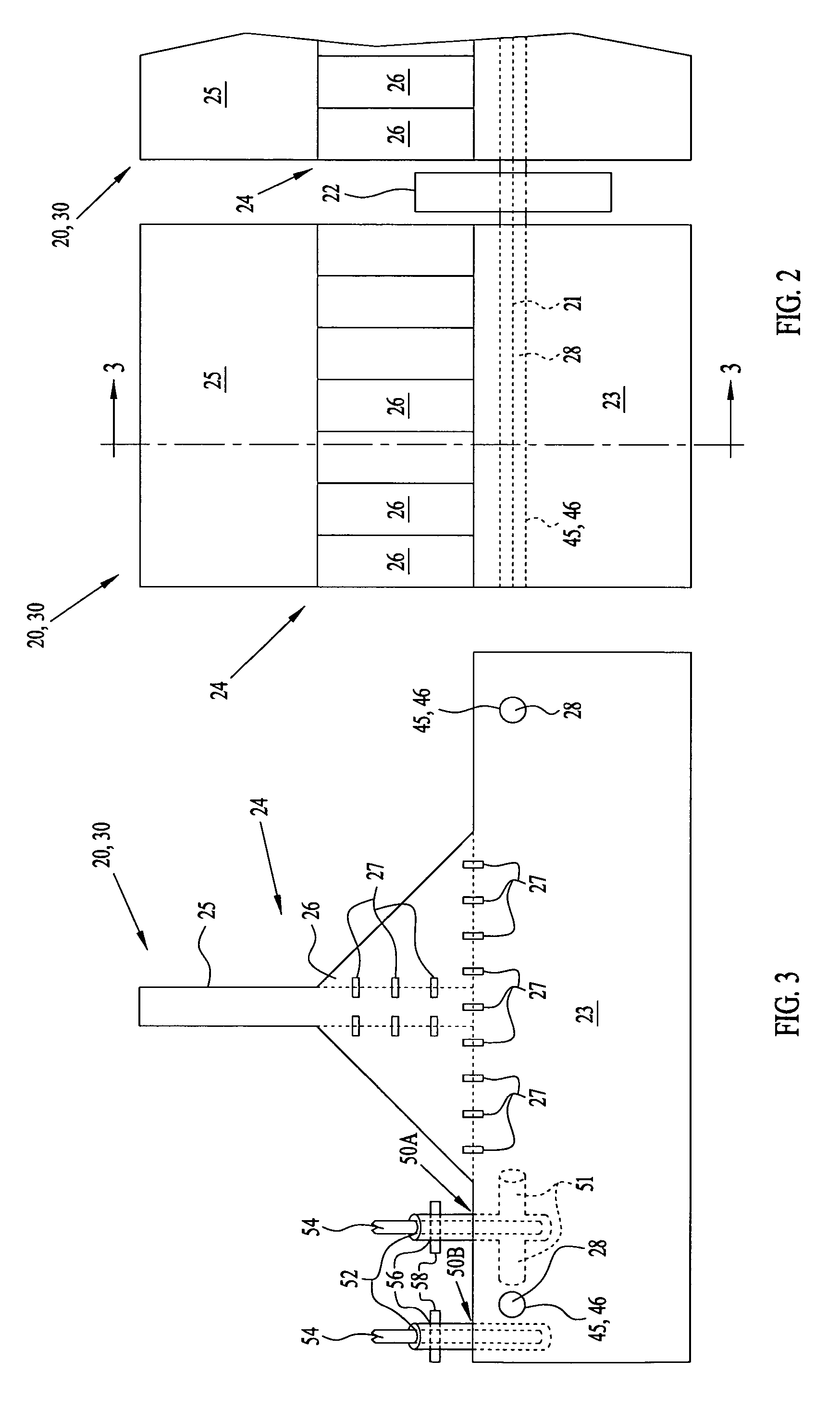
[0025]Referring to FIGS. 1, 2, and 3, a barrier 10 for small boats floats on water 6 and extends across a waterway surface 7 or along a perimeter 8 bordering marine facilities such as supply or fueling docks, warehouses, anchored ships, etc. that are to be closed to traffic from small boats. Barrier 10 has a sufficient number of cast flotation modules 20 on lines 21 extending through adjacent flotation modules 20 to reach across waterway surface 7 or along the length of perimeter 8 to anchoring systems 12. Anchoring systems 12 include an anchor 13 and lines 14 that are connected to lines 21 not only at opposite ends of barrier 10, but may be coupled to lines 21 along the length of barrier 10. Lines 21 and 14 can include stretchable nylon or other non-corrosive energy absorbing material or wire rope or chain to help absorb the energy of impacting craft. At least one resilient cushion structure 22 is interposed between adjacent flotation modules 20 to prevent them from knocking agains...


PUM


Abstract

A barrier for small boats has a plurality of flotation modules on lines extending across a waterway. The flotation modules are cast from a buoyant concrete mixture of cement, water, beaded forms of expanded polystyrene, and polypropylene fibers that is non-water-absorbing, crushable, not susceptible to failure in shear, and has a density lighter than water. The mixture can have cement with the beads in a ratio of about 1:3.5 by volume, the water with the cement in a ratio of about 0.5 (1:2) by weight and the fibers with the cement in a ratio of about 1:141 by weight. Lines pass thru the flotation modules and slip upon impact of a flotation module by a speeding boat, and the buoyant concrete mixture crushes to absorb some energy of the impact. The barrier is relatively low cost, can be made next to a waterway from readily available materials by unskilled workers and is deployed in a minimum amount of time.

Description

STATEMENT OF GOVERNMENT INTEREST[0001]The invention described herein may be manufactured and used by or for the Government of the United States of America for governmental purposes without the payment of any royalties thereon or therefor.BACKGROUND OF THE INVENTION[0002]This invention relates to a barrier for small boats. More particularly, the invention is to a cost effective floating barrier for small boats that is cast from low density concrete.[0003]Marine facilities including ships are vulnerable to sabotage by explosive laden small boats. Different access-obstructing structures have been placed on the water with varying degrees of effectiveness.[0004]One floating structure has a series of elongate, voluminous hollow water pipes sealed at their ends that are strung across an access way. Additional hollow pipes are welded to and across them for added buoyancy and to stabilize a partitioned wall held above the water that hopefully deters, or deflects encroaching small boats. This...

Claims


Application Information

Patent Timeline
IPC IPC(8): B63B35/44
CPCB63B5/16E02B15/08E02B3/062B63B35/34B63B2231/66B63B2231/62
Inventor JENNINGS, NYAL
Owner THE UNITED STATES OF AMERICA AS REPRESENTED BY THE SECRETARY OF THE NAVY
Why Eureka
Try Eureka