
Aluminum heat exchanger

a heat exchanger and aluminum technology, applied in indirect heat exchangers, refrigeration components, light and heating apparatus, etc., can solve the problems of reduced adsorption ability of adsorbent, increased manufacturing cost and size and weight of devices, and increased the cost of additional equipment, so as to prevent the generation of hydrogen

Inactive Publication Date: 2006-02-07
DENSO CORP
View PDF9 Cites 10 Cited by
  • Summary
  • Abstract
  • Description
  • Claims
  • Application Information

AI Technical Summary

Benefits of technology

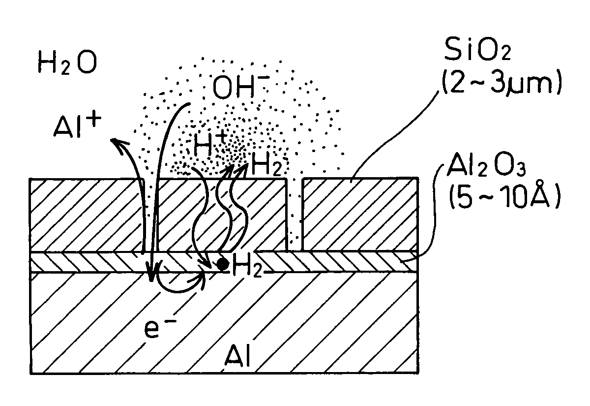
[0010]In an aluminum heat exchanger of the present invention, a film which does not permit moisture to pass therethrough is formed on the surface of the aluminum heat exchanger arranged in a casing, and several ppm to a hundred and several tens ppm of inorganic oxide negative ions are added solely or in combination to the refrigerant enclosed in the casing. With this structure, in an aluminum heat exchanger arranged in the casing, as a matter of cause, no aluminum is released from the portion which is always in contact with the vaporized refrigerant (water vapor). Regarding the portion coated with the film, which is periodically in contact with the refrigerant (water) and the vaporized refrigerant (water vapor), it takes long time for the refrigerant (water) which has permeated through flaws of the film to reach the surface of the aluminum, due to the film formed on the aluminum surface. Therefore, if the refrigerant is transformed into the vapor (water vapor) before it reaches the aluminum surface, no hydrogen gas is generated. Regarding the portion which is always in contact with the refrigerant (water), the negative ions in the refrigerant repair the flaws of the film, so that the generation of the hydrogen can be certainly prevented.

Problems solved by technology

Consequently, the water vapor cannot be adsorbed and thus, the adsorption ability of the adsorbent is decreased.
Accordingly, the amount of evaporation of the refrigerant is reduced thus leading to reduction of the refrigerating ability.
The provision of additional equipment increases the manufacturing cost and the size and weight of the devices, and reduces the performance.
However, in the adsorber of the prior art, it is very difficult to form on the heat exchanger a film which perfectly prevents generation of hydrogen, i.e., a film which can perfectly intercept the water.
Also, it is difficult to conduct an inspection to prove that the film provided on the surface of the heat exchanger is perfect.

Method used


Image

  • Aluminum heat exchanger
  • Aluminum heat exchanger
  • Aluminum heat exchanger

Examples


Embodiment Construction

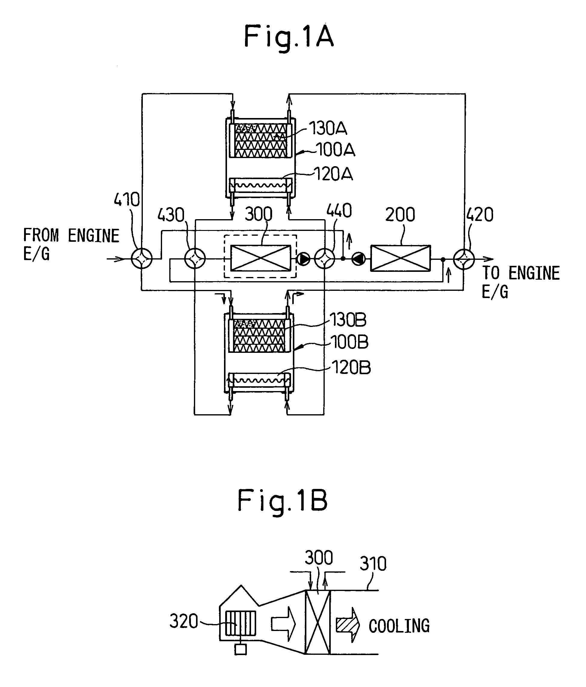
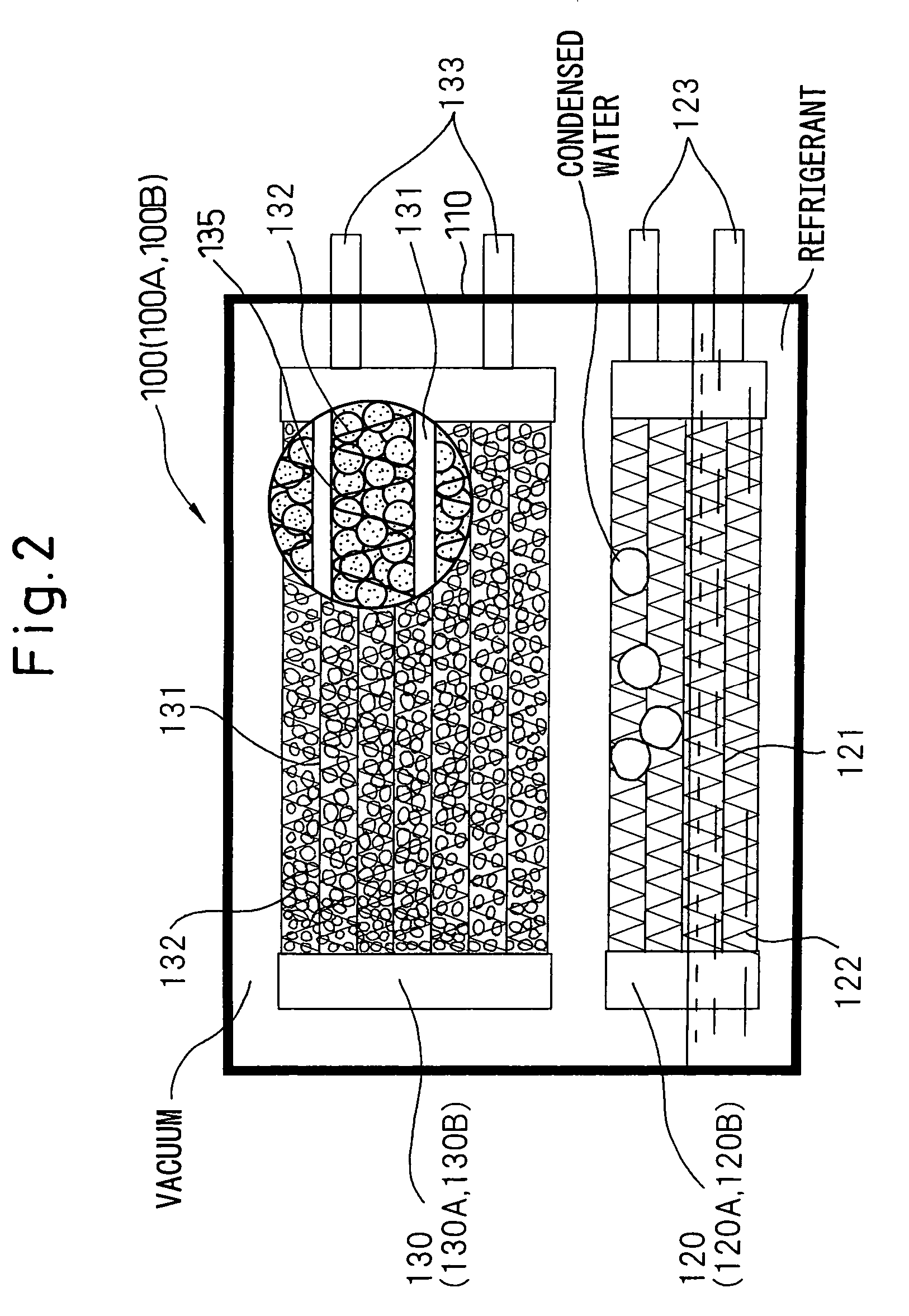
[0026]Embodiments of the present invention, in which an aluminum heat exchanger is used as an adsorber for an adsorption type refrigerator, will be explained below with reference to the drawings. FIG. 1 schematically shows an aluminum heat exchanger of the present invention, applied to an adsorption type air conditioner. In FIG. 1A, numeral 100 represents an adsorber in this embodiment. At least two adsorbers 100 are provided, of which the upper adsorber 100 in the drawing is a first adsorber 100A and the lower adsorber 100 is a second adsorber 100B. Likewise, first and second heat exchangers 120, 130 in the first adsorber 100A are indicated by 120A and a 130A, respectively, and first and second heat exchangers 120, 130 in the second adsorber 100B are indicated by 120B and 130B, respectively.

[0027]Numeral 200 represents an external heat exchanger which performs a heat exchange between a heat medium (in this embodiment, fluid comprising water and an ethylene glycol-based antifreeze, ...


PUM

PropertyMeasurementUnit
thicknessaaaaaaaaaa
temperatureaaaaaaaaaa

Abstract

In an adsorber for an adsorption type refrigerator of the present invention, aluminum heat exchangers 120, 130 arranged in a casing 110 are provided with films which do not permit moisture to pass therethrough, such as SiO3 films, anodic oxide coating films and several ppm to a hundred and several tens of ppm of inorganic negative ions such as PO43−, SiO32− are added in the water enclosed in the casing.

Description

FIELD OF THE INVENTION[0001]The present invention relates to an aluminum heat exchanger which can be used as an adsorber for use with, for instance, an adsorption type refrigerator or a heat pipe.DESCRIPTION OF THE RELATED ART[0002]An adsorption type refrigerator utilizes a function of an adsorbent, such as zeolite or silica gel, to adsorb water vapor, wherein refrigerating power is obtained by cooling a liquid-phase refrigerant, such as water, enclosed in a substantially evacuated casing, due to a heat of evaporation (latent heat of evaporation) which is generated when the liquid is adsorbed. Hereinafter, an adsorber in which evaporation of the liquid-phase refrigerant and adsorption of the vapor-phase refrigerant occur will be referred to as an adsorber in an adsorption process.[0003]For example, when the entirety of the liquid-phase refrigerant is evaporated, or, the adsorption ability of the adsorber is saturated (the adsorption amount has reached the limit), so that the pressur...

Claims


Application Information

Patent Timeline
Patent Type & Authority Patents(United States)
IPC IPC(8): F28F19/00F25B35/04F28F19/02F25B47/00F28D15/02F28F13/18F28F21/08
CPCF25B35/04F28F13/18F25B47/003Y02B30/64Y02B30/62Y02A30/27Y02B30/00
Inventor NAGASHIMA, HISAOOTOBE, JUNJIISHII, KATSUYA
Owner DENSO CORP
Learn More