Polymeric electroluminescent device using an emitting layer of nanocomposites

Inactive Publication Date: 2006-02-07
KOREA INST OF SCI & TECH
View PDF9 Cites 26 Cited by
  • Summary
  • Abstract
  • Description
  • Claims
  • Application Information

AI Technical Summary

Benefits of technology

[0008]In order to resolve the above problems, it is therefore an objective of the present invention to provide a polymeric electroluminescent device with suppressed pho

Problems solved by technology

However, the encapsulation technique has the disadvantage that it must be performed in a limited temperature range, which is lower than the decomposition temperature of polymer, and is thus difficult to apply to flexible display devices.
However, those metal particles or semiconductor particles known up to now have

Method used


Image

  • Polymeric electroluminescent device using an emitting layer of nanocomposites
  • Polymeric electroluminescent device using an emitting layer of nanocomposites
  • Polymeric electroluminescent device using an emitting layer of nanocomposites

Examples


Embodiment Construction

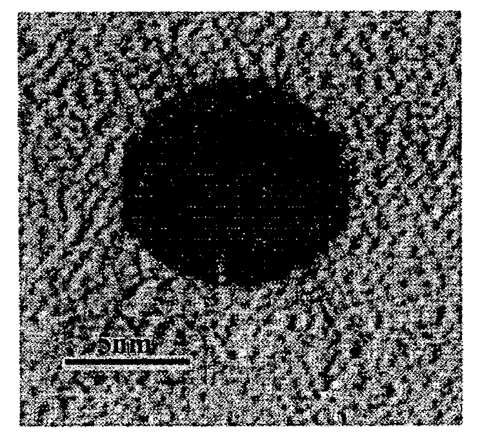
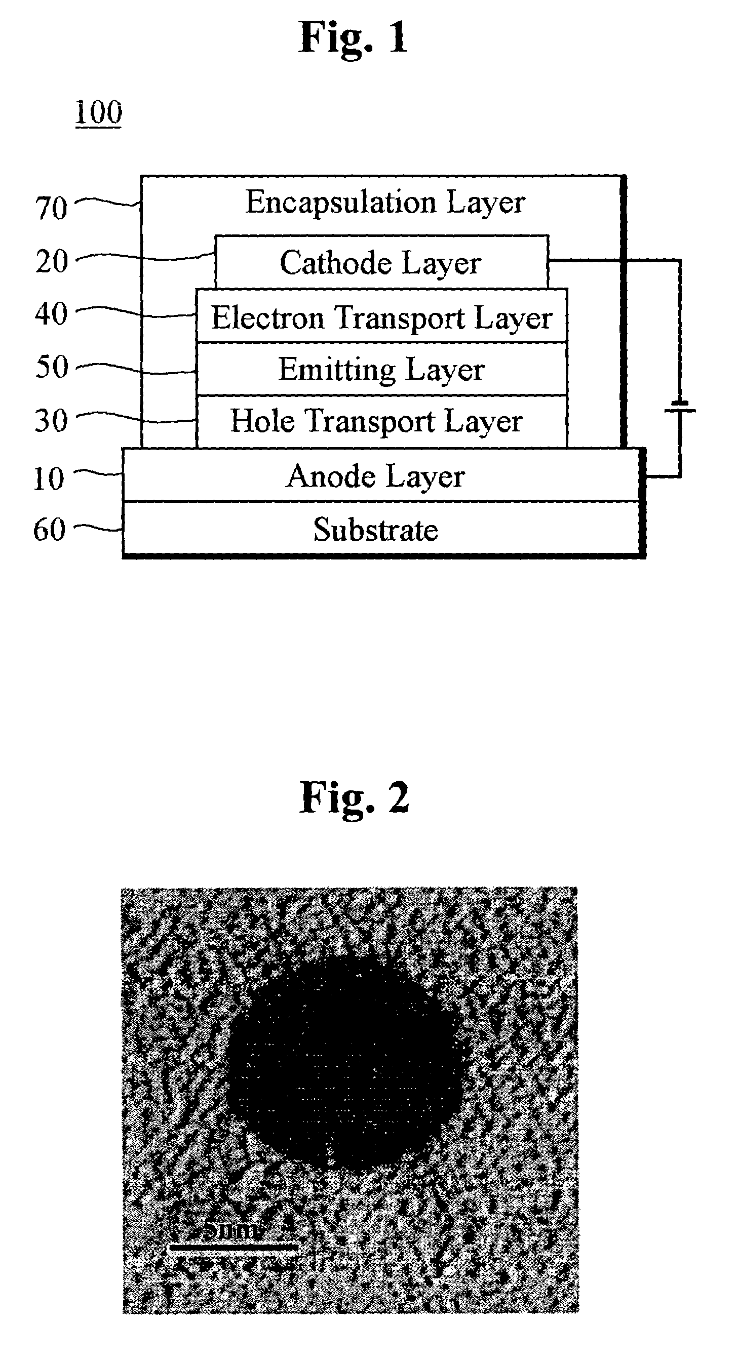
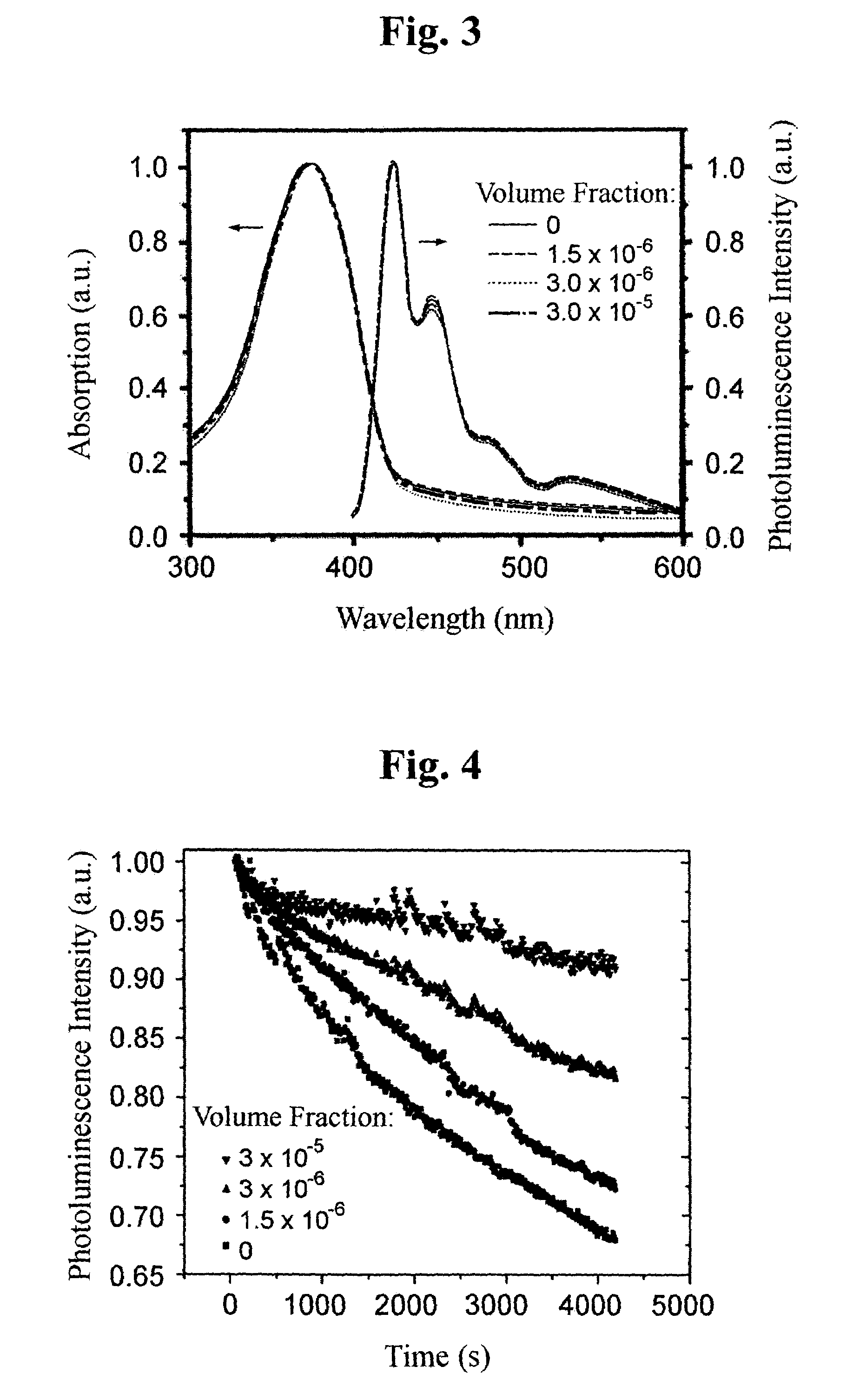
[0018]A composite of nanoparticles and a luminescent polymer, nanocomposite, is used as an emitting layer of a polymeric electroluminescent device in accordance with the present invention. Metal nanoparticles such as Au, Ag, Pt, Ni, Fe, Co and Ge, which are on the order of 1–100 nm in size, are mixed with a luminescent polymer such as poly(dihexylfluorene), poly(phenylenevinylene) and poly(dioctylfluorene), which generates light with wavelengths of 400–800 nm, in a volume fraction of 1×10⁻⁹ to 0.1. As a result, the metal nanoparticles are in resonance with the triplet excitons of the luminescent polymer and absorb the energy of the triplet excitons. A description is provided below of an embodiment using a nanocomposite, which is a mixture of a blue-light-emitting polymer such as poly(dioctylfluorene) and gold nanoparticles, as an emitting layer of a polymeric electroluminescent device in accordance with the present invention.

[0019]For the formation of gold nanoparticles, a 30 mM aqu...


PUM

PropertyMeasurementUnit
Sizeaaaaaaaaaa
Sizeaaaaaaaaaa
Wavelengthaaaaaaaaaa

Abstract

A polymeric electroluminescent device suppresses photo-oxidation and enhances luminous stability and efficiency by using a nanocomposite of a luminescent polymer and metal nanoparticles as its emitting layer.

Description

FIELD OF THE INVENTION[0001]The present invention relates to an organic electroluminescent device, and more particularly, to a polymeric electroluminescent device using a nanocomposite emitting layer of a luminescent polymer mixed with metal nanoparticles.BACKGROUND OF THE INVENTION[0002]Organic electroluminescence is a phenomenon wherein, as electrons and holes are injected into an organic thin film, respectively, from a cathode and anode, excitons, which emit light having a particular wavelength, are generated within the organic thin film. Devices using this phenomenon have several advantages. They are lightweight, thin, self-luminous, operate at a low power, and have a rapid switching velocity.[0003]Among such organic electroluminescent devices, a polymeric electroluminescent device, in which a thin film is formed by a spin-coating technique, as reported by a group of British researchers led by Professor R. H. Friend in 1990, merits particular attention due to its cost-effectiven...

Claims


Application Information

Patent Timeline
IPC IPC(8): H01J63/04H01L51/50C09K11/06H01L51/00H05B33/00H05B33/14
CPCB82Y20/00B82Y30/00C09K11/06H05B33/14H01L51/5012C09K2211/185C09K2211/188H01L51/0038H01L51/0039C09K2211/187H10K85/115H10K85/114H10K50/11
Inventor KIM, YOUNG CHULKIM, JAI KYEONGYU, JAE-WOONGPARK, O OKPARK, JONG HYEOKLIM, YONG TAIK
Owner KOREA INST OF SCI & TECH
Why Eureka
Try Eureka