Detector configurations for optical metrology

a technology of optical metrology and configuration, applied in the direction of optical radiation measurement, direct flow property measurement, instruments, etc., can solve the problems of contaminating the wafer, affecting the accuracy of the measurement, and the limited information of this type of detection cannot be typically used to deriv

Inactive Publication Date: 2006-02-07
KLA CORP
View PDF34 Cites 56 Cited by
  • Summary
  • Abstract
  • Description
  • Claims
  • Application Information

AI Technical Summary

Benefits of technology

[0012]In a first embodiment, a narrowband light source such as a laser is used to generate a probe beam. The polarized beam is focused onto the sample in a manner to create a large spread of angles of incidence. The probe beam light is passed through a quarter waveplate for retarding the phase of one of the polarization states of the beam with respect to the other polarization state of the beam. A polarizer is provided for creating interference between the two polarization states in the reflected probe beam.
[0014]In either case, the output of the segments lying substantially along one radial axis is subtracted from the output of the segments lying substantially along an orthogonal radial axis. In order to gain additional information, the output of the sectors lying along a third radial axis located midway between the first two orthogonal axes (i.e. at 45 degrees) is subtracted from the sectors lying along a fourth radial axis, perpendicular to the third axis. This extra information obtained corresponds to an orientation essentially shifted by 45 degrees from the first measurements. When all the measurements are combined, the sample may be more accurately evaluated. This extra information can be supplied to conventional fitting algorithms to evaluate characteristics including thin film thickness, index of refraction and extinction coefficient. In addition, geometrical parameters of structures formed on semiconductors such as line width, spacing, and side wall angle and shape can also be evaluated. These calculations can be made using the measurements directly. Alternatively, the measurements can be used to derive the ellipsometric parameters Ψ and Δ which are then used to evaluate the sample.

Problems solved by technology

However, the limited information from this type of detection cannot typically be used to derive both of the ellipsometric parameters, Ψ and δ. U.S. Pat. No. 5,586,411, discloses that it would be possible to derive such information if one of polarizers were rotated and multiple measurements taken.
For example, moving parts often create particulates that can contaminate the wafer.

Method used


Image

  • Detector configurations for optical metrology
  • Detector configurations for optical metrology
  • Detector configurations for optical metrology

Examples


Embodiment Construction

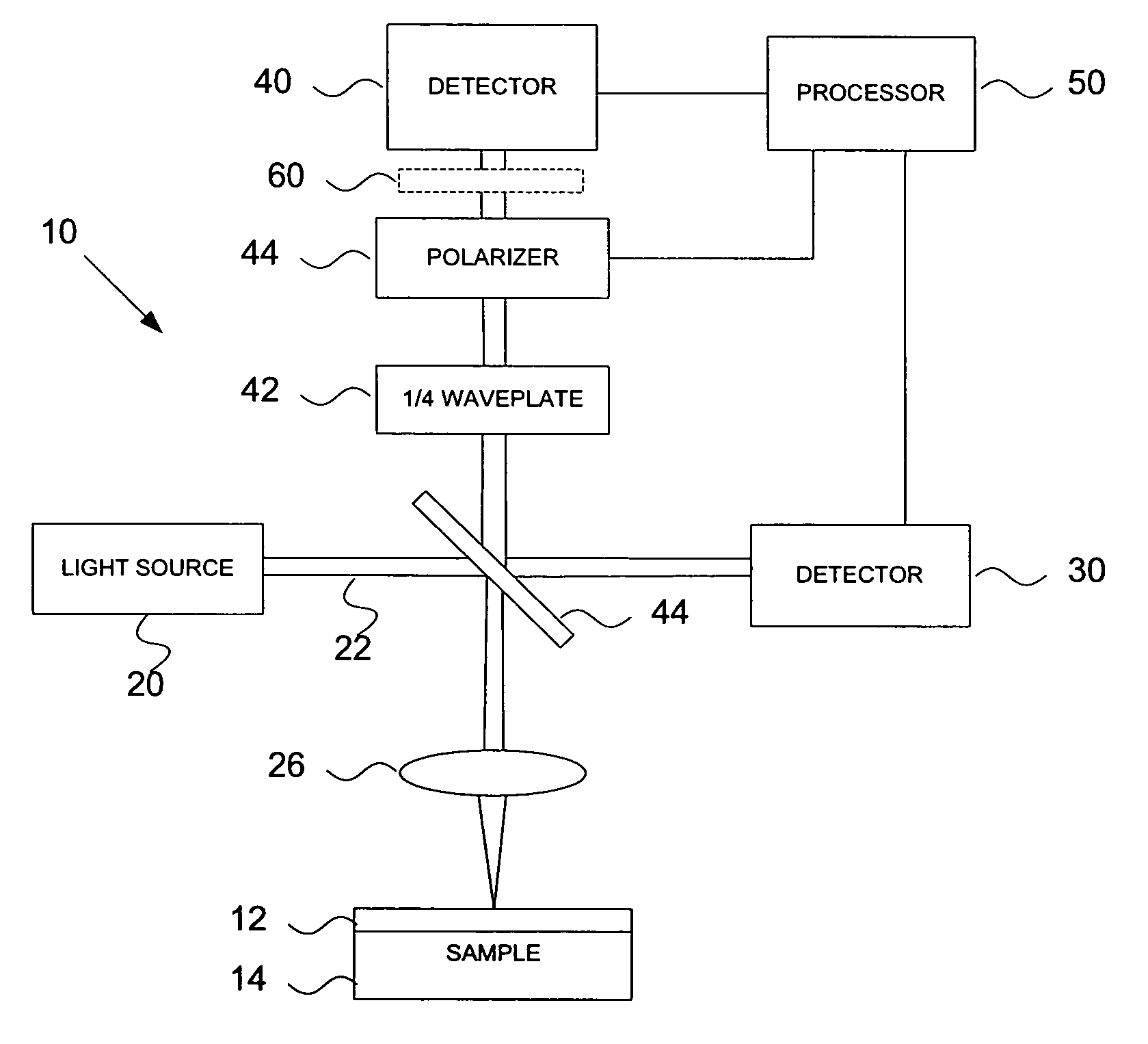
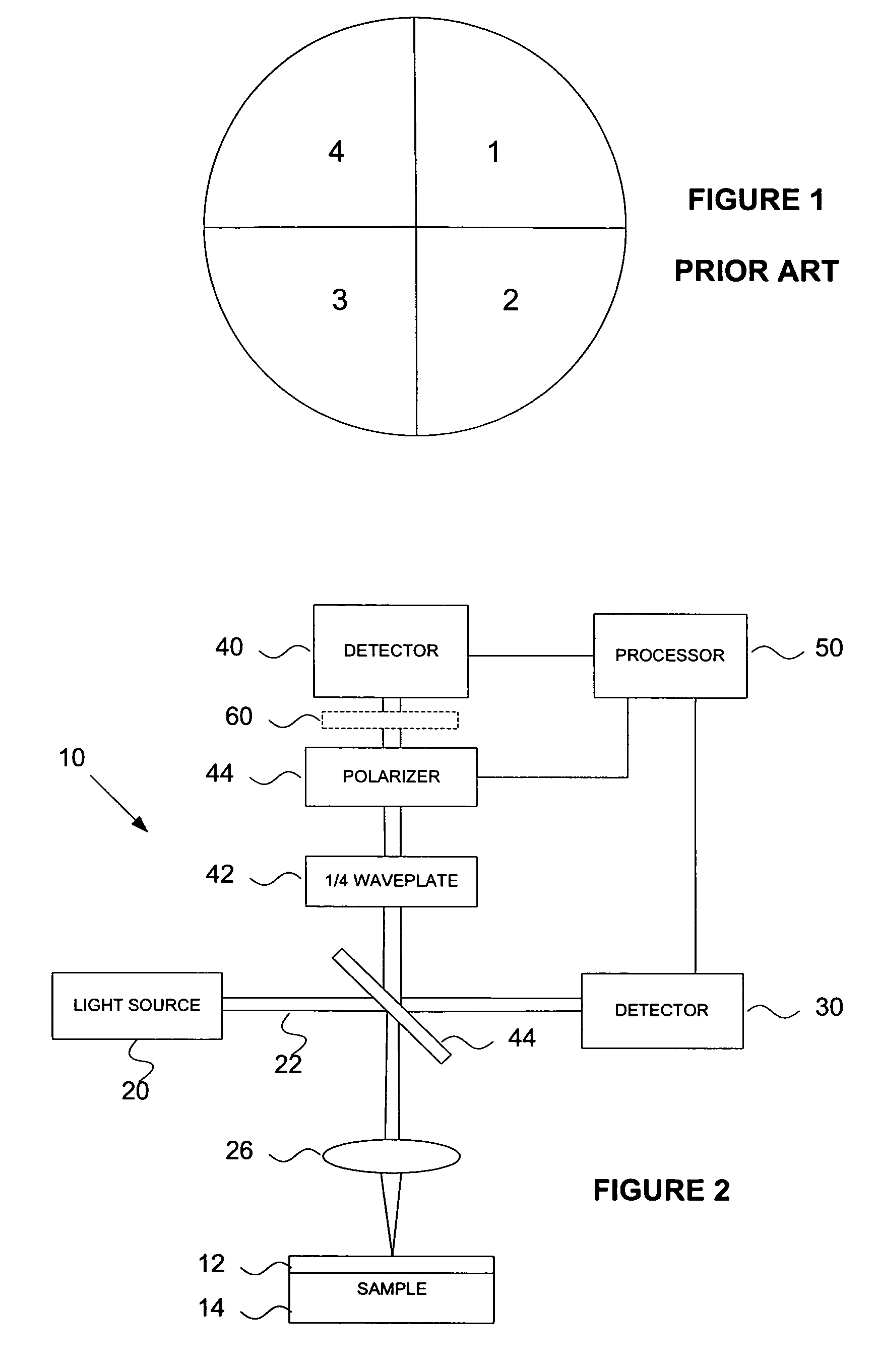
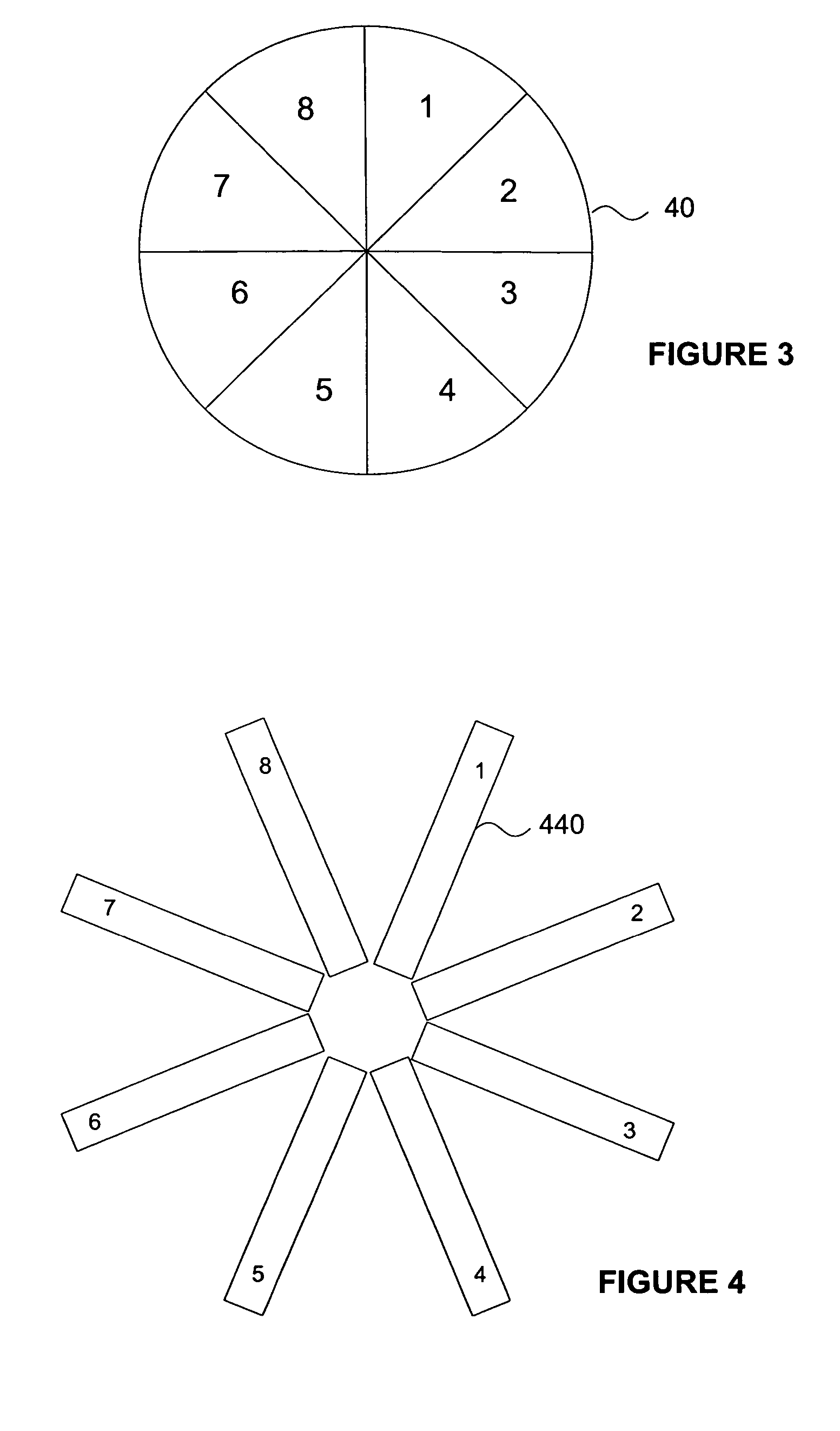
[0029]Turning to FIG. 2, an apparatus 10 is illustrated for performing the method of the subject invention. The apparatus lay out for this embodiment is essentially the same as that described in U.S. Pat. No. 5,181,080, except that the detector is configured with eight segments (FIG. 3) rather than four segments as in the prior art (FIG. 2). The apparatus is designed to evaluate characteristics at the surface of a sample 14, such as thin film layers 12 and / or structural features such as critical dimensions.

[0030]In this embodiment, apparatus 10 includes a light source 20 for generating a probe beam 22 of radiation. One suitable light source is a solid state laser diode which emits a linearly polarized beam having a stable, known and relatively narrow bandwidth. Probe beam 22 is turned towards the sample 14 with a 50 / 50 beam splitter 44. The probe beam is focused onto the surface of the sample with a lens 26. In the preferred embodiment, lens 26 is defined by a spherical, microscope ...


PUM

PropertyMeasurementUnit
diameteraaaaaaaaaa
sizeaaaaaaaaaa
angleaaaaaaaaaa

Abstract

An apparatus is disclosed for obtaining ellipsometric measurements from a sample. A probe beam is focused onto the sample to create a spread of angles of incidence. The beam is passed through a quarter waveplate retarder and a polarizer. The reflected beam is measured by a detector. In one preferred embodiment, the detector includes eight radially arranged segments, each segment generating an output which represents an integration of multiple angle of incidence. A processor manipulates the output from the various segments to derive ellipsometric information.

Description

PRIORITY[0001]This application is a continuation of U.S. Ser. No. 10 / 696,269, filed Oct. 29, 2003, now U.S. Pat. No. 6,836,328 which is in turn a continuation of U.S. Ser. No. 10 / 137,606, filed May 2, 2002, now U.S. Pat. No. 6,678,046, which claimed priority to Provisional Application Ser. No. 60 / 315,514, filed Aug. 28, 2001, the disclosure of which is incorporated herein by reference.BACKGROUND OF THE INVENTION[0002]There is ongoing interest in expanding and improving the measurement of semiconductor wafers. A number of optical metrology tools have been developed for non-destructively evaluating the characteristics of thin films formed on semiconductors during the fabrication process. More recently, optical metrology systems have been proposed for analyzing the geometry of small periodic structures (critical dimensions) on semiconductors.[0003]Typical optical tools include reflectometry (both single wavelength and spectroscopic) and ellipsometry (again, both single wavelength and s...

Claims


Application Information

Patent Timeline
Patent Type & Authority Patents(United States)
IPC IPC(8): G01N11/06G01J4/04
CPCG01B11/0641G01N21/211G01J4/04G01N2021/213
Inventor OPSAL, JON
Owner KLA CORP
Why Eureka
Try Eureka