A blue phase liquid crystal display device

A blue-phase liquid crystal and display device technology, applied in optics, lenses, instruments, etc., can solve the problems of large difference in electric field strength, large deflection and high working voltage, and achieve the effect of good electric field uniformity and good electric field strength

Active Publication Date: 2016-03-30
BOE TECH GRP CO LTD
View PDF3 Cites 0 Cited by
  • Summary
  • Abstract
  • Description
  • Claims
  • Application Information

AI Technical Summary

Problems solved by technology

[0005] In the blue-phase liquid crystal panel in the prior art, a plurality of electrodes 2 are arranged on the array substrate 1, and an electric field is formed by the potential difference between two adjacent electrodes 2, and the distribution of the electric field is as follows: figure 1 As shown, if the distance from the electrode 2 is different, the difference in electric field intensity is relatively large. Therefore, in the blue phase liquid crystal layer 4 between the array substrate 1 and the color filter substrate 3, the blue phase liquid crystal molecules 42 in the lower layer that are closer to the array substrate 1 are affected. The force of the electric field is larger, and the deflection is larger; while the blue phase liquid crystal molecules 41 in the upper layer farther away from the array substrate 1 are subjected to a smaller force of the electric field, and the deflection is smaller. In order to increase the electric field between the array substrate 1 and the color filter substrate 3 The uniformity of the electric field direction and the electric field strength difference between the lower layer blue phase liquid crystal molecules 42 closer to the array substrate 1 and the upper layer blue phase liquid crystal molecules 41 farther away from the array substrate 1 and the electric field strength are minimized, and the electrode 2 needs to be applied higher working voltage
[0006] Therefore, blue-phase liquid crystal panels and blue-phase liquid crystal display devices in the prior art generally have the problem of high power consumption due to high operating voltage.

Method used


Image

  • A blue phase liquid crystal display device
  • A blue phase liquid crystal display device
  • A blue phase liquid crystal display device

Examples


Embodiment Construction

[0040] The following will clearly and completely describe the technical solutions in the embodiments of the present invention with reference to the accompanying drawings in the embodiments of the present invention. Obviously, the described embodiments are only some, not all, embodiments of the present invention. Based on the embodiments of the present invention, all other embodiments obtained by persons of ordinary skill in the art without making creative efforts belong to the protection scope of the present invention.

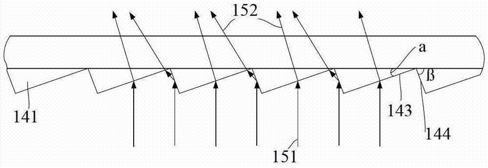
[0041] In the following discussion, in order to facilitate the description of the structure and principle of the blue-phase liquid crystal panel, the concept of "backlight module" is introduced in the article. The backlight module 15 is as follows: Figure 6 shown in .

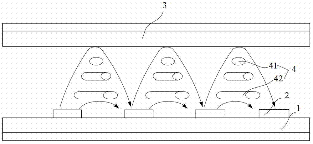
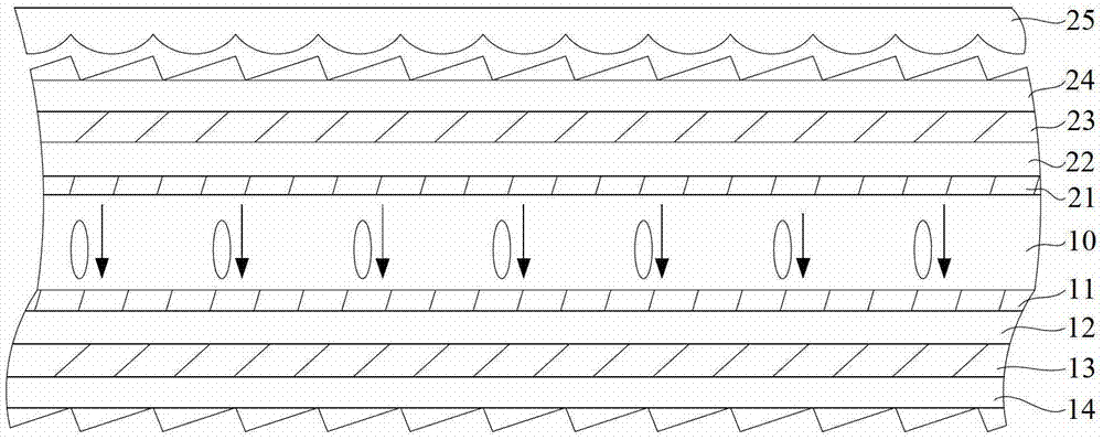
[0042] Such as figure 2 and image 3 as well as Figure 6 As shown, the blue-phase liquid crystal panel provided by the present invention includes a first substrate 12, a second substrate ...


PUM

PropertyMeasurementUnit
angleaaaaaaaaaa

Abstract

The invention discloses a blue-phase liquid crystal display device, which comprises a backlight module and a blue-phase liquid crystal panel, wherein the blue-phase liquid crystal panel comprises a first substrate, a second substrate and a blue-phase liquid crystal located between the first substrate and the second substrate Layer, the light output direction of the backlight module is perpendicular to the first substrate; the blue phase liquid crystal panel also includes a first electrode on one side of the first substrate, a first substrate coupling film on the other side of the first substrate; The second electrode on one side of the substrate; the first electrode and the second electrode form a vertical electric field; the first substrate coupling film changes the direct light of the backlight module into oblique light having a predetermined included angle with the direction of the vertical electric field. The above blue phase liquid crystal display device improves the uniformity of light emitted by the blue phase liquid crystal panel in the blue phase liquid crystal display device, and increases the display viewing angle of the blue phase liquid crystal panel.

Description

technical field [0001] The invention relates to the field of display technology, in particular to a blue-phase liquid crystal panel and a blue-phase liquid crystal display device. Background technique [0002] Blue-phase liquid crystals are used in liquid crystal display devices to obtain high-performance TFT-LCD displays. Compared with traditional liquid crystals, blue-phase liquid crystals have their outstanding advantages: the theoretical response time of blue-phase liquid crystal displays can reach below the ms level, and the response speed is ordinary 10 times that of nematic liquid crystal, so it can be applied to display devices that require fast response speed, such as color sequential display; blue phase liquid crystal does not require an alignment layer, which not only simplifies the manufacturing process, but also reduces production costs, etc. widespread attention of the people. [0003] However, the blue-phase liquid crystals in the current blue-phase liquid cr...

Claims


Application Information

Patent Timeline
Patent Type & Authority Patents(China)
IPC IPC(8): G02F1/1343G02F1/1335G02F1/137
CPCG02B3/005G02B5/045G02F1/133504G02F1/133567G02F1/13793G02F1/134363G02F1/133562G02F1/133528G02F1/133553G02F1/1336G02F1/133621G02F1/134309
Inventor 李会崔贤植严允晟徐智强
Owner BOE TECH GRP CO LTD
Why Eureka
Try Eureka