Displacement sensor

a sensor and displacement technology, applied in the field of displacement sensors, can solve the problems of positional change, measurement object irregularities in reflection intensity, and inability to maintain the size of the light spot, and achieve the effect of improving the resolution of the position detection element and simple structur

Inactive Publication Date: 2006-02-07
ORMON CORP
View PDF9 Cites 7 Cited by
  • Summary
  • Abstract
  • Description
  • Claims
  • Application Information

AI Technical Summary

Benefits of technology

[0019]In contrast, in the case when the light-path-length sweeping mechanism makes the light-path length longer, the light-converging positions of the reflected luminous fluxes from the irradiation luminous fluxes and the measuring object are allowed to shift toward respectively opposite sides to the above-mentioned positions with respect to the light-converging position of the reflected luminous fluxes in the neutral state of the light-path-length sweeping mechanism; thus, in the same manner as the case of short light-path length, the luminous fluxes on the light-shielding mask become comparatively larger, resulting in a reduction in the amount of receiving light.
[0075]The luminous fluxes, released from the reflection-face-use light-projection unit, may be arranged so as to be converged to form a spot having a fine size on the light-receiving face of the position detection element; this arrangement is preferable, since the resolution of the position detection element is improved. Moreover, these luminous fluxes may be applied so as to be always included in the reflection face even when the reflection face is displaced; this arrangement is more preferable since it is possible to prevent the position of the center of gravity of the spot being irregularly varied on the position detection element, and consequently to eliminate the necessity of exception process and correction.

Problems solved by technology

In this displacement sensor in the triangulation surveying system, it is not possible to maintain the size of the light spot applied on the measuring object at a fine spot size corresponding to a diffraction limit.
Here, any measuring object has irregularities in reflection intensity due to fine roughness on the surface and color unevenness as long as it does not have a complete mirror surface.
Consequently, luminance irregularities occur in the reflected light spot on the measuring object, resulting in a positional change in the center of gravity of the light-receiving spot on the position detection element.
This causes a measuring error, and disturbs measuring processes with high precision.
However, in the displacement sensor of this type, since the sweeping process is carried out by using the lens attached to a tuning fork, there is a limitation in increasing the sweeping frequency.
This is because, the lens, which needs to have a predetermined size so as to reduce the spot diameter that is determined by the diffraction limit in order to maintain a sufficient amount of receiving light, cannot be miniaturized.
This causes a reduction in the natural frequency, making it difficult to increase the sweeping frequency.
In an attempt to measure the shape of a measuring object with high precision, although it depends on applications, the total measuring time often reaches an order of seconds to minutes, causing a step that limits the number of products.
When some of the inspection processes are omitted in order to shorten the total measuring time, defective products might escape from rejection, and when the number of averaging processes of measured values is reduced, there is degradation in the measuring precision.
Moreover, since the natural frequency is determined integrally by the lens and tuning fork, and since the sweeping frequency is virtually determined by the natural frequency, it is not possible to easily alter the detection distance and the displacement measuring range by exchanging lenses.
This is because the exchange of lenses requires the alteration in the sweeping frequency, causing changes in the processing circuits, the tuning-fork-driving coils and the like.
When a number of lenses are added, the outside shape becomes larger, causing high costs.
In the case when the sensor is redesigned and manufactured in response to the detection distance and displacement measuring range corresponding to the changed measuring object and shape of the device, high developing costs and the like are required, also resulting in high costs.

Method used


Image

  • Displacement sensor
  • Displacement sensor
  • Displacement sensor

Examples


Embodiment Construction

[0130]Referring to attached Figures, the following description will discuss embodiments of a displacement sensor of the present invention in detail.

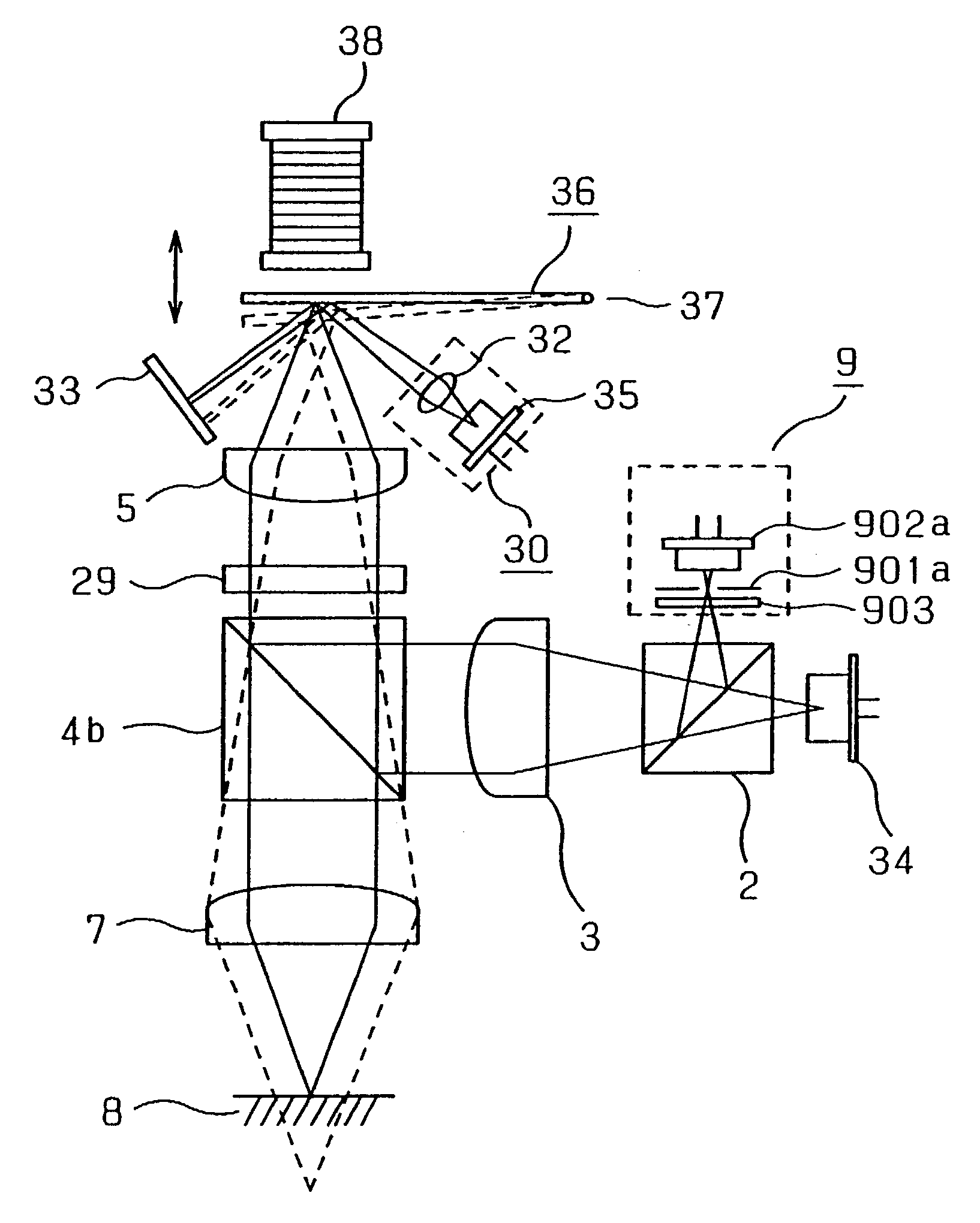
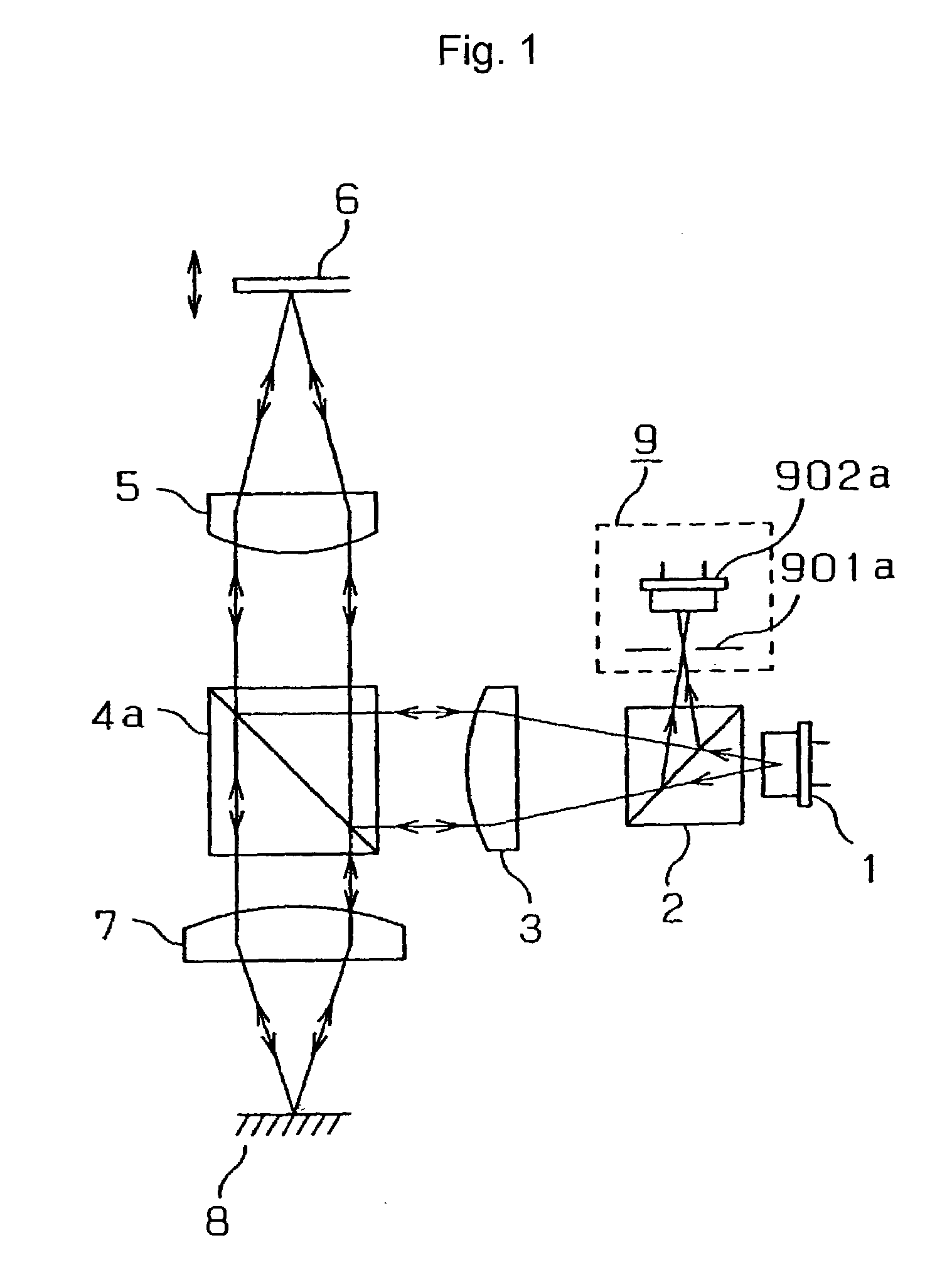
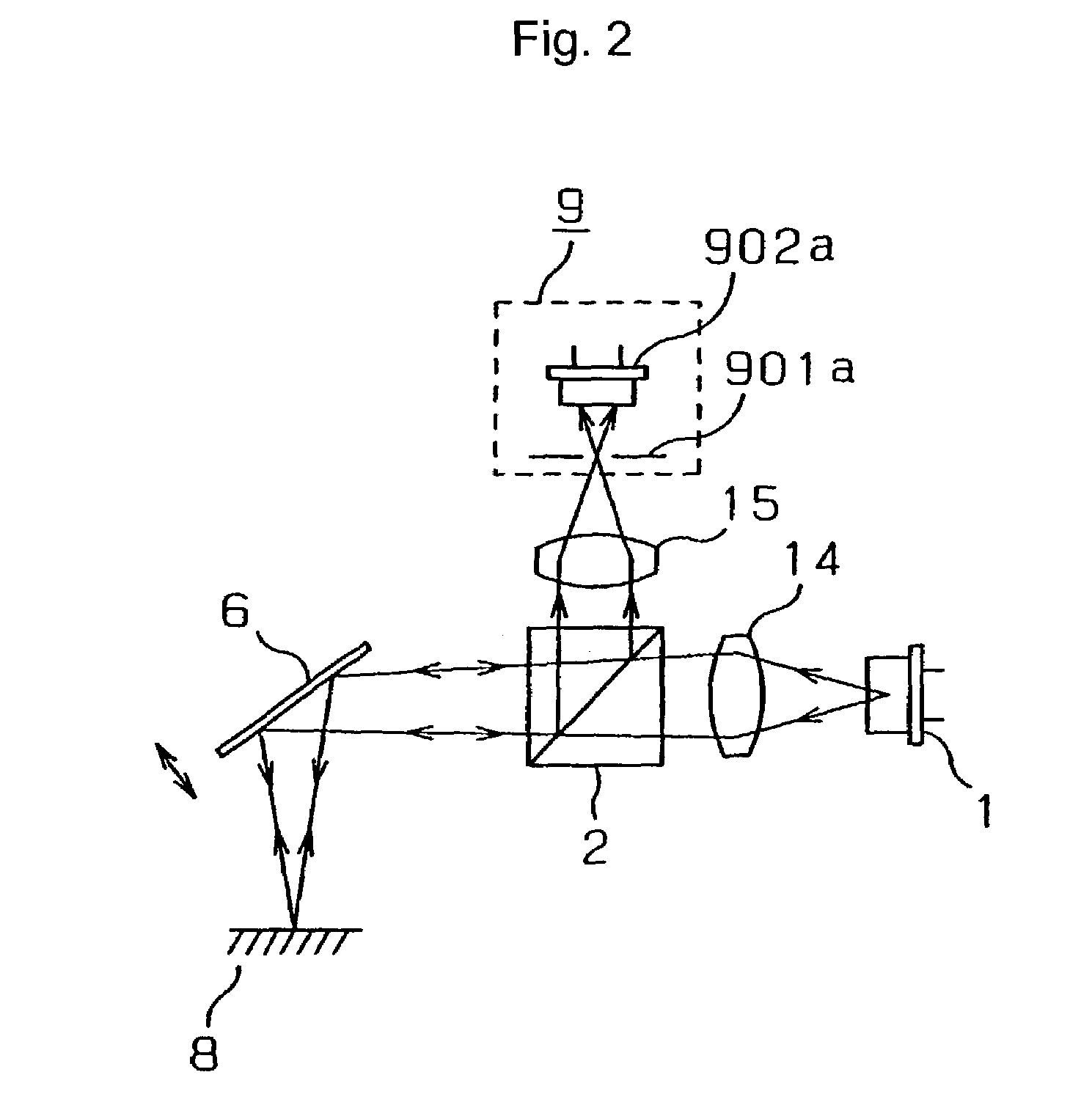
[0131]FIG. 31 shows a layout of an optical system of the present displacement sensor. The optical system of the present sensor is provided with a red semiconductor laser 34 serving as a light projecting unit, a cube half mirror 2 serving as “a first light-path control element”, a lens 3 commonly serves as a collimate lens and a light-receiving lens, an intermediate lens 5, an objective lens 7 serving as “a third light-converging element”, a polarizing beam splitter 4b serving as “a second light-path control element”, a ¼-wavelength plate 29 with respect to the wavelength of light released by the red semiconductor laser 34, a cantilever beam 36 and an electromagnet 38 serving as a light-path length sweeping mechanism, a pinhole 901a serving as a light-shielding mask of a light-receiving unit, a photodiode 902a serving as a light-receiving...


PUM


Abstract

A displacement sensor is provided with: a light-projection unit; a light-receiving unit having a light-shielding mask and a light-receiving element; a first light-converging element which converges luminous fluxes released from the light-projection unit on a measuring object; a second light-converging element which converges reflected luminous fluxes on the light-receiving unit; a first light-path control element which allows a projection-light light axis and a receiving-light light axis to be coaxially set on the measuring object side; and a light-path length sweeping mechanism which continuously changes a light-path length from the light-projection unit to the measuring object and a light-path length from the measuring object to the light-receiving unit.

Description

BACKGROUND OF THE INVENTION[0001]1. Field of the Invention[0002]The present invention relates to a displacement sensor which measures a displacement of a measuring object in a non-contact state.[0003]2. Description of the Background Art[0004]In the technical field such as FA (factory automation), many displacement sensors have been used in positional controlling processes for manufacturing devices used for manufacturing products or positional controlling processes for products with respect to the manufacturing devices, or inspection processes for products and the like. These displacement sensors generally use a triangulation surveying system. In this system, light is applied to a measuring object, and the light reflected by the measuring object is detected by a position detection element and the like, and based upon the positional change in the center of gravity of a light-receiving spot on the position detection element that is changed in accordance with the displacement of the mea...

Claims


Application Information

Patent Timeline
Patent Type & Authority Patents(United States)
IPC IPC(8): G01B11/24G01B11/00G01B11/02
CPCG01B11/026
Inventor UNO, TETSUYATAKIMASA, HIROAKISUGA, TAKAHIRO
Owner ORMON CORP
Why Eureka
Try Eureka