Projection display system using polarized light

a technology of projection display and polarized light, which is applied in the field of projection display systems, can solve the problems of large number of components in this architecture, large physical size of the system, and requirement of a large back working distance for the projection lens, and achieve the effect of small back working distance from the projection lens and reduced manufacturing cos

Inactive Publication Date: 2006-02-07
SHARP KK
View PDF45 Cites 33 Cited by
  • Summary
  • Abstract
  • Description
  • Claims
  • Application Information

AI Technical Summary

Benefits of technology

[0044]The projection display systems of the present invention have one or more of the following advantages: a small back-working distance from the projection lens; a projection path free from crossed dichro

Problems solved by technology

However, the large number of components in this architecture is cumbersome, and necessitates a relatively large physical size of the system.
The most serious drawback to these systems is the requirement of a large back working distance for the projection lens.
The minimum distance referred to here is strictly valid only for systems of very high f/# and thus impractical due to low light throughput.
However, these advantages are relatively minor.
One system difficulty not addressed by the configuration in FIG. 2 is the reduction in the back working distance of the projection lens.
Unfortunately, crossing plate dichroics 62, 64, introduces a problem because the operation at the intersection of the two plates is usually disrupted by the thickness of the plates, producing a seam in the middle of the image, where the images of the three LCD panels are totally or partially obscured by the plate intersection.
Also, the transmission/reflection characteristics of dichroic filters are significantly different for p- and s-polarizations, which results in the color characteristics of the whole projector being difficult to control.
However, this assembly is precise and the color cube co

Method used


Image

  • Projection display system using polarized light
  • Projection display system using polarized light
  • Projection display system using polarized light

Examples


Embodiment Construction

[0060]1. Projection Display System

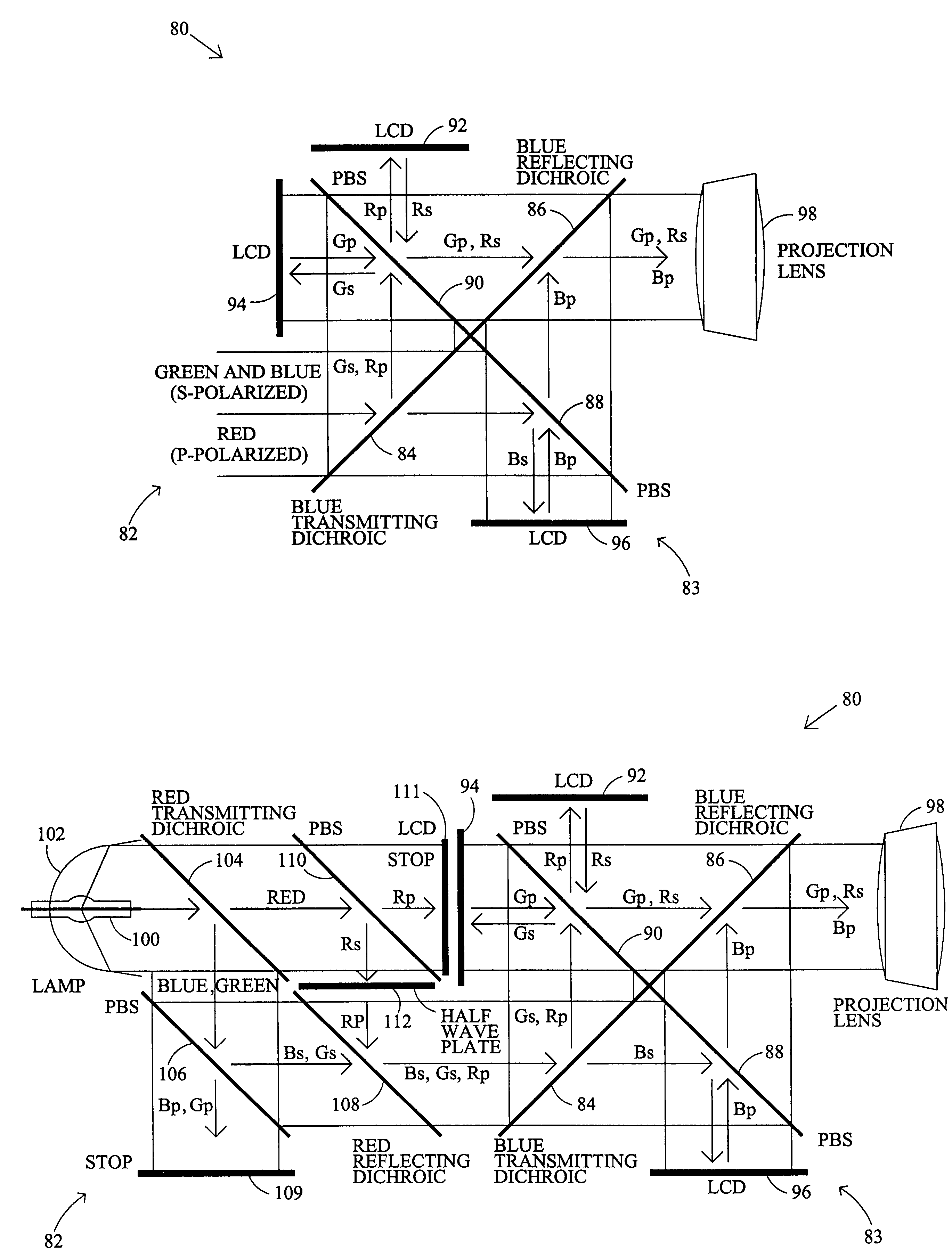
[0061]An exemplary embodiment of the projection display system of the present invention is shown generally at 80 in FIG. 4. System 80 includes a light source 82 and a projection system 83. Projection system 83 includes two dichroic filters (DF) 84, 86, and two polarizing beam splitters (PBS) 88, 90, to split up the incoming white light from light source 82 into red-green-blue (RGB) components before directing each light beam component to a specific light valve, or liquid crystal display (LCD), 92, 94, 96. LCDs 92, 94, 96 each provide a light-component-specific image, which is illuminated by the light beam component and reflected from the face of the LCD, carrying a color image component. The color image components are then recombined, and the reflected light is directed to projection lens 98.

[0062]A requirement for proper operation of projection system 83 is that the input illumination is pre-filtered and polarized so that the green and blue distrib...


PUM


Abstract

A projection display system using polarized light comprises a light source for generating a light beam having at least two light components, wherein the light components are polarized and at least one of the light components is polarized differently than another of the light components. The projection display system has a projection system having a plurality of polarized light modulators, each modulator generating a light-component-specific image associated with one of the light components. The projection display system also has a projection lens for projecting an image combined from the light-component-specific images from the modulators. The present invention also provides a polarization converter for use with a light source that generates a light beam having at least two light components. The polarization converter comprises an optics array capable of separating the light beam into at least one light component having a polarization that is different than another light component.

Description

BACKGROUND OF THE INVENTION[0001]This invention relates to projection display systems which use reflective spatial light modulators, and specifically, to such systems which incorporate reflective liquid crystal devices, as well as to projection display systems which incorporate polarization converters.[0002]1. Projection Display Systems[0003]The system shown in FIG. 1 illustrates the essential components of the optical portion of a projection display system having three reflective spatial light modulators in the form of liquid crystal display (LCD) panels, also referred to as liquid crystal light valves (LCLV). The prior art system, depicted generally at 10 includes a light source 12, an illumination mechanism for collecting the light and concentrating it onto the light valves, shown generally at 14, a polarizing mechanism for polarizing the light, if the light valves modulate via polarization effects, shown generally at 16, a splitting mechanism for splitting the illumination into ...

Claims


Application Information

Patent Timeline
IPC IPC(8): G02B27/14G02F1/1335G03B21/26G03B33/12G02B27/28G02F1/13G02F1/13357G03B21/00H04N5/74H04N9/31
CPCG02B27/123G02B27/145G02B27/149H04N9/3197H04N5/7441H04N9/3105H04N9/3167G02B27/283
Inventor SAMPSELL, JEFFREY B.FLORENCE, JAMES M.
Owner SHARP KK
Why Eureka
Try Eureka