Converter and a method for controlling a converter

a converter and converter technology, applied in the field of converters, can solve the problems of difficult and often impossible to turn off the converter, short-circuit current, etc., and achieve the effect of efficient and rapid detection of short-circuit curren

Inactive Publication Date: 2006-02-07
ABB (SCHWEIZ) AG
View PDF5 Cites 18 Cited by
  • Summary
  • Abstract
  • Description
  • Claims
  • Application Information

AI Technical Summary

Benefits of technology

[0008]The object of the present invention is to make possible an efficient and rapid detection of a short-circuit current occurring in a current valve of a converter.

Problems solved by technology

Such short-circuit currents may for instance ensue in that a prohibited turn-on of a current valve takes place at the same time as a current valve with opposite polarity is conducting, which for instance may be caused by an error in the control equipment that controls the turn-on and turn-off of the semiconductor components of turn-off type of the current valves.
When the current saturation level has been reached in a semiconductor component of turn-off type, it will be difficult and often impossible to turn it off.

Method used


Image

  • Converter and a method for controlling a converter
  • Converter and a method for controlling a converter
  • Converter and a method for controlling a converter

Examples


Embodiment Construction

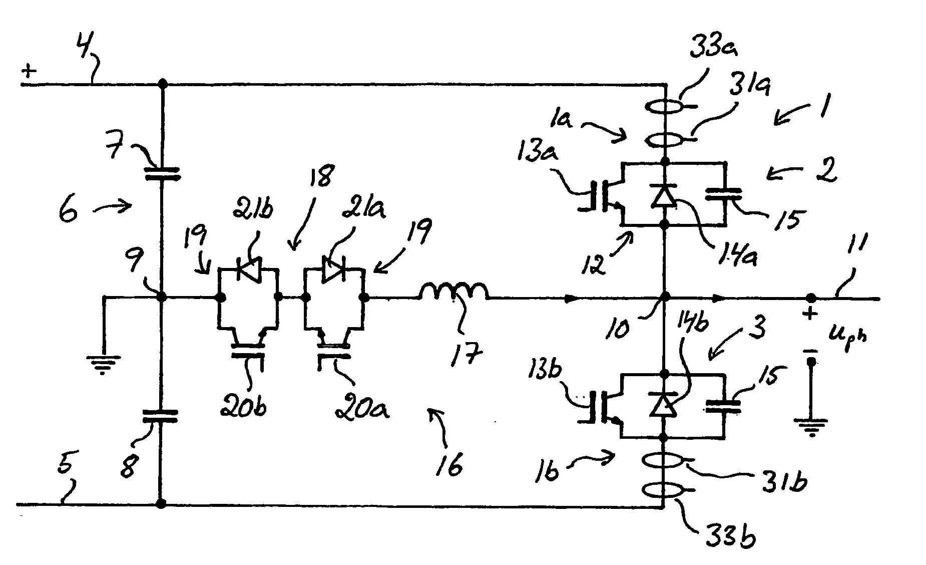
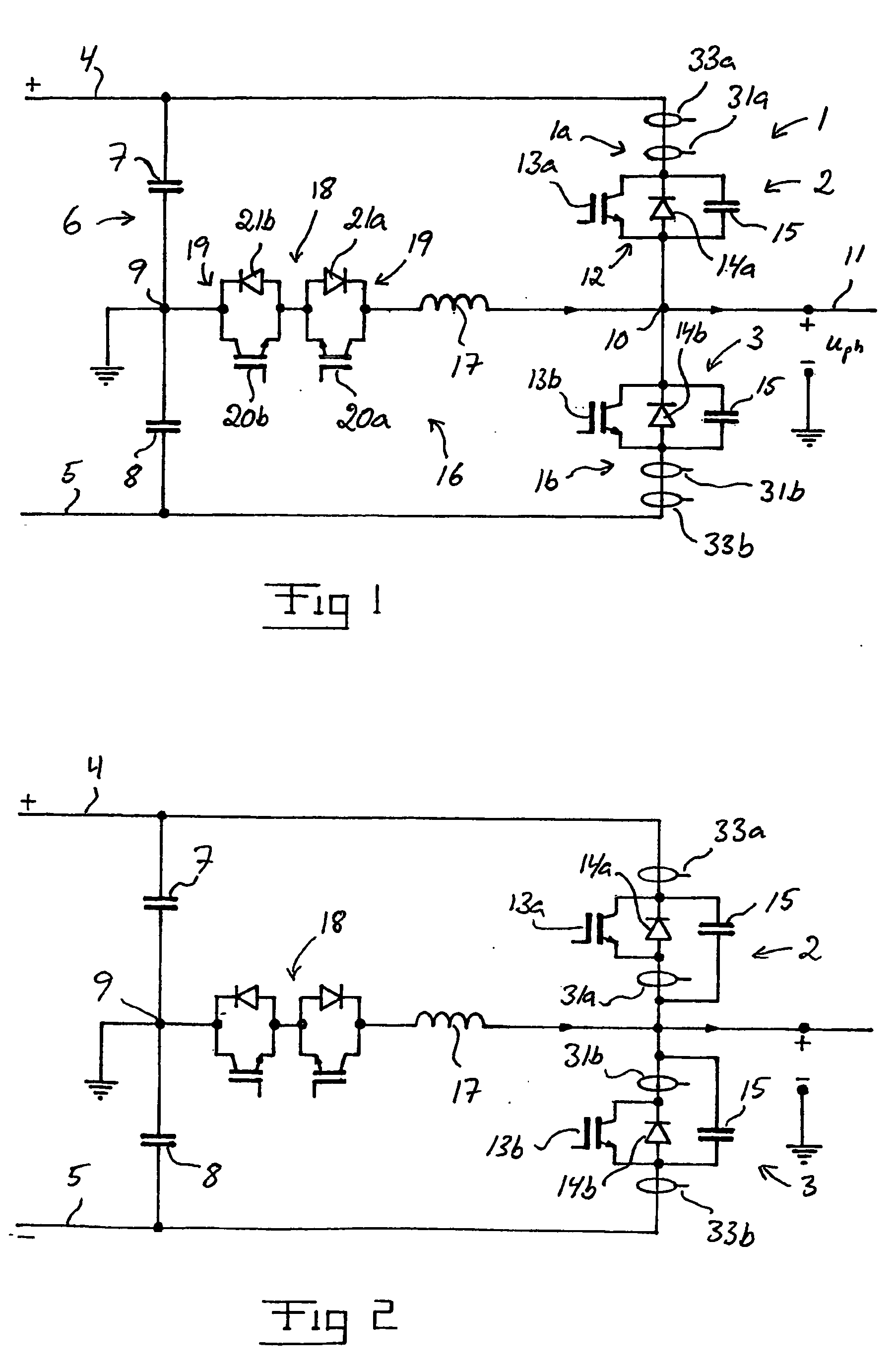
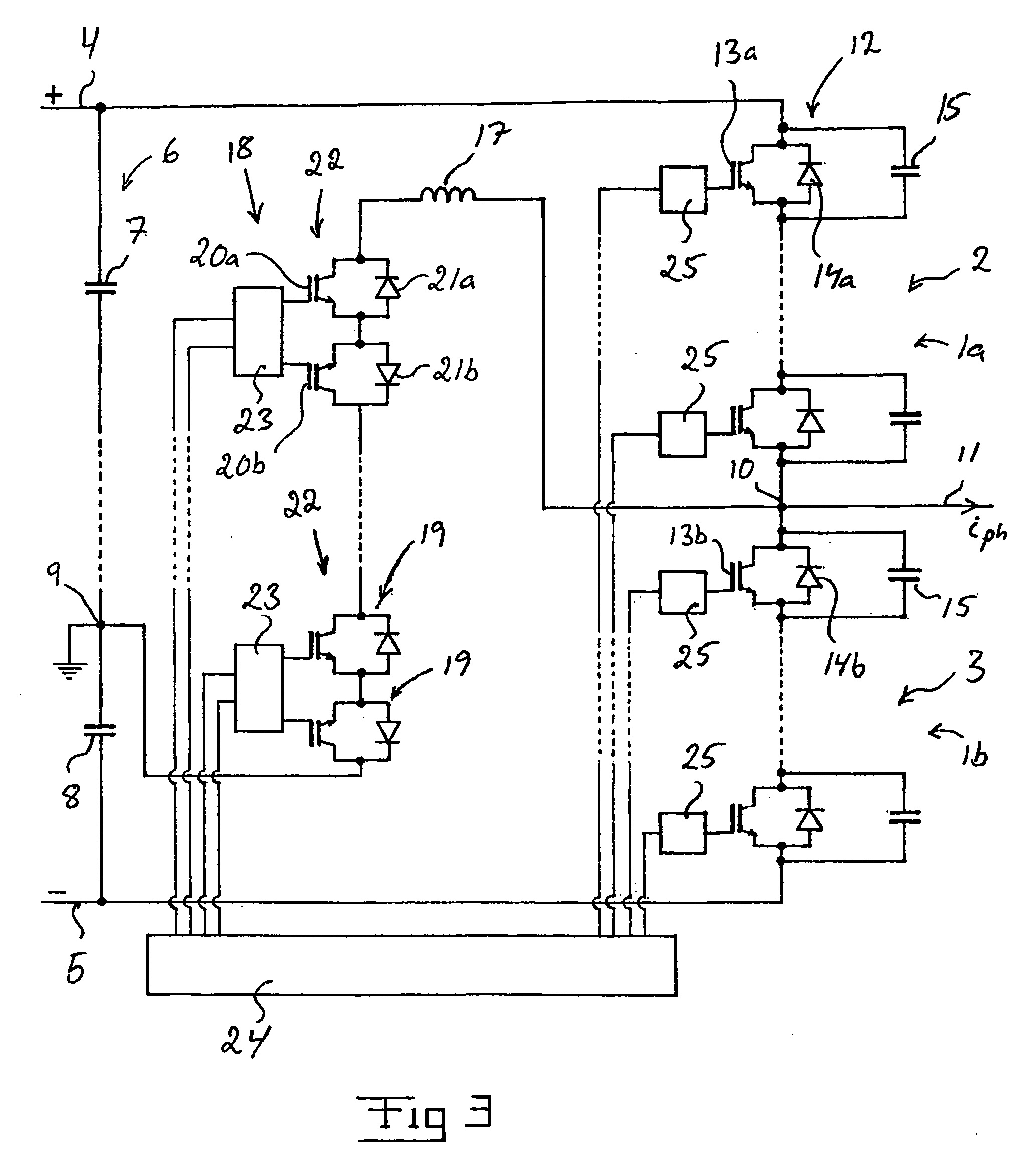
[0027]Converters according to different embodiments of the invention are illustrated in FIGS. 1–3. The respective converter is here a so-called VSC-converter. In FIGS. 1–3, only the part of the converter that is connected to one phase of an alternating voltage phase line is shown, the number of phases normally being three, but this may also constitute the entire converter when it is connected to a single phase alternating voltage network. The shown part of the converter constitutes a so-called phase leg, and a converter adapted for instance to a three-phase alternating voltage network comprises three phase legs of the type shown.

[0028]The phase leg of the converters 1 illustrated in FIGS. 1–3 has two current valves 2, 3 connected in series between the two poles 4, 5 of a direct voltage side of the converter. A direct voltage intermediate link 6 comprising at least two so-called intermediate link capacitors is provided between the two poles 4, 5. In the illustrated converters, the in...


PUM


Abstract

The invention relates to a converter provided with a resonant circuit (16), which converter comprises a device (31) for measuring the derivative (dI/dt) of the current through the current valves 82, 3) and a detection device (32) co-operating with said measuring device (31) for detecting a short-circuit in the converter, the detection device (32) being adapted to detect a short-circuit current when the current derivative (dI/dt) measured by the measuring device (31) is equal to or exceeds a stipulated current derivative limit value (dI/dtlim) during a length of time exceeding a stipulated time limit value (tlim). The invention also relates to a method for controlling such a converter.

Description

FIELD OF THE INVENTION AND PRIOR ART[0001]The present invention relates to a converter according to the preamble of claim 1 and a method for controlling such a converter.[0002]The invention particularly relates to a VSC-converter. A VSC-converter for connection between a direct voltage network and an alternating voltage network is previously known e.g. from the thesis “PWM and control of two and three level high voltage source converters” by Anders Lindberg, Royal Institute of Technology, Stockholm, 1995, in which publication a plant for transmitting electric power through a direct voltage network for high-voltage direct current (HVDC), while utilizing such converters, is described. Before the creation of this thesis, plants for transmitting electric power between a direct voltage network and an alternating voltage network have been based upon the use of network commutated CSC (Current Source Converter)-converters in stations for power transmission. However, in this thesis a totally...

Claims


Application Information

Patent Timeline
Patent Type & Authority Patents(United States)
IPC IPC(8): H02H7/00H02M1/00H02M7/48
CPCH02M7/4826H02M1/32H02M2001/0009H02M1/0009H02M7/4811
Inventor BIJLENGA, BOLUNDBERG, PETERJONSSON, TOMASJOHANSSON, NICKLASRAMEZANI, ESIE
Owner ABB (SCHWEIZ) AG
Why Eureka
Try Eureka