Image forming apparatus, optical writing device, and controlling method thereof

a technology of optical writing device and image forming apparatus, which is applied in the direction of optical radiation measurement, visual presentation using printers, instruments, etc., can solve the problem achieve the effect of short time for initializing the laser array, and simple initialization of the laser array

Inactive Publication Date: 2006-02-14
RICOH KK
View PDF8 Cites 3 Cited by
  • Summary
  • Abstract
  • Description
  • Claims
  • Application Information

AI Technical Summary

Benefits of technology

[0010]According to the present invention, when the output power of one of the lasers changes (for example, increase), the change of the output power of the laser can be monitored by using the synchronization signal. Specifically, the control unit determines that the output power of the laser under adjustment reaches the predetermined value when the synchronization signal is detected. This scheme makes it easy to monitor the output powers of the lasers during adjustment, and still ensures sufficiently reliable power adjustment up to the line APC process.
[0011]According to the present invention, the control unit adjusts the output powers of the lasers to be the desired value one by one, that is, after completion of adjustment of one laser, start adjustment of the next laser. Further, during the adjustment of one laser, the control unit monitors the output power of the laser using the synchronization signal generated by the laser under adjustment itself, but not by any other lasers. Specifically, the control unit stops the power adjustment when the synchronization signal is detected twice. Therefore, this scheme makes it simple to initialize the laser array, and makes the time for initializing the laser array short. Further, it is not necessary to stop the power adjustment of any lasers in order to generate a synchronization signal during the adjustment, making the initialization of the image forming apparatus smoothly.
[0012]According to the present invention, the number of the lasers that need to be adjusted can be appropriately changed. As a result, it is possible to make the initialization operation suitable to the system configuration.

Problems solved by technology

Therefore, this scheme makes it simple to initialize the laser array, and makes the time for initializing the laser array short.

Method used


Image

  • Image forming apparatus, optical writing device, and controlling method thereof
  • Image forming apparatus, optical writing device, and controlling method thereof
  • Image forming apparatus, optical writing device, and controlling method thereof

Examples


Embodiment Construction

[0019]Below, preferred embodiments of the present invention are explained with reference to the accompanying drawings.

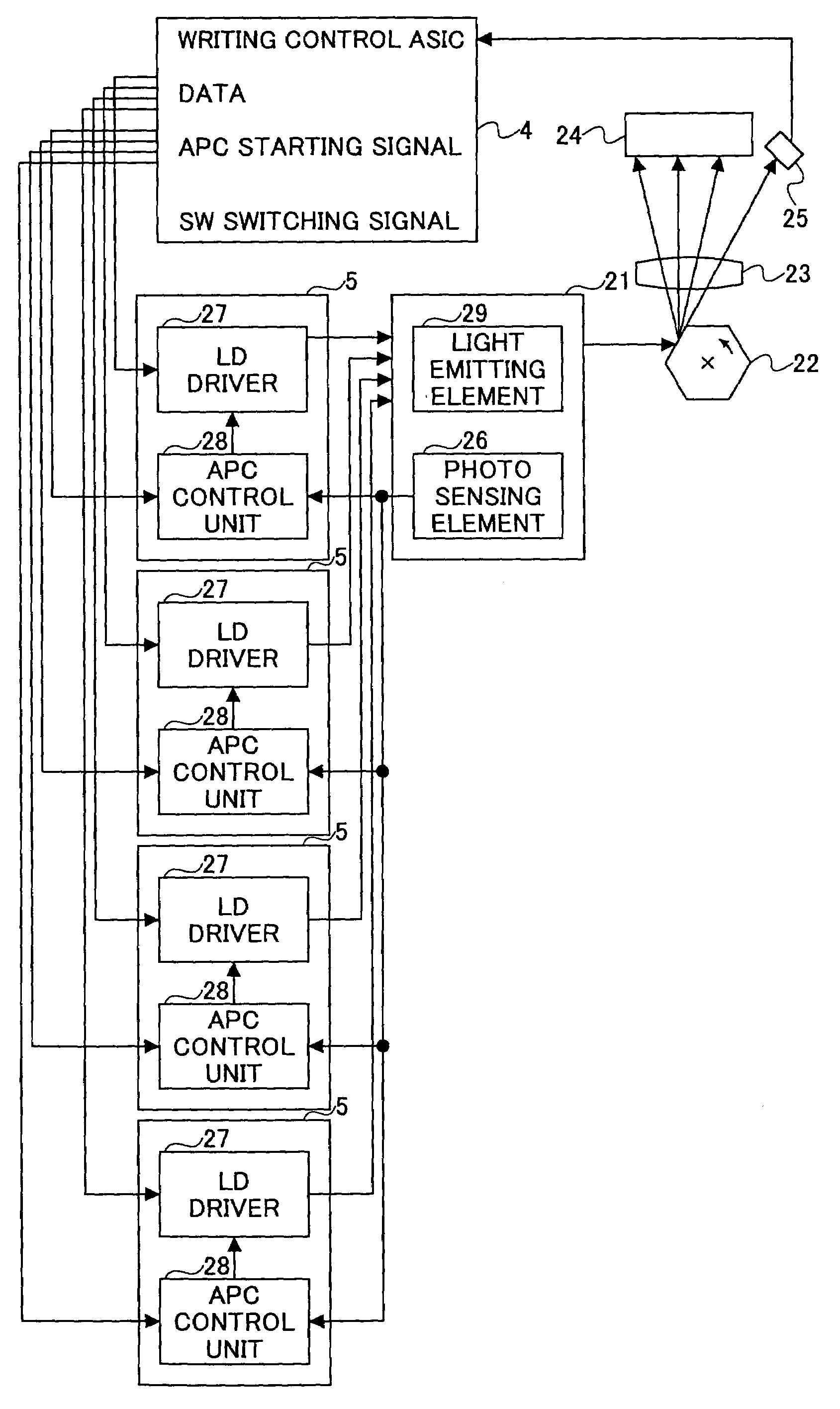
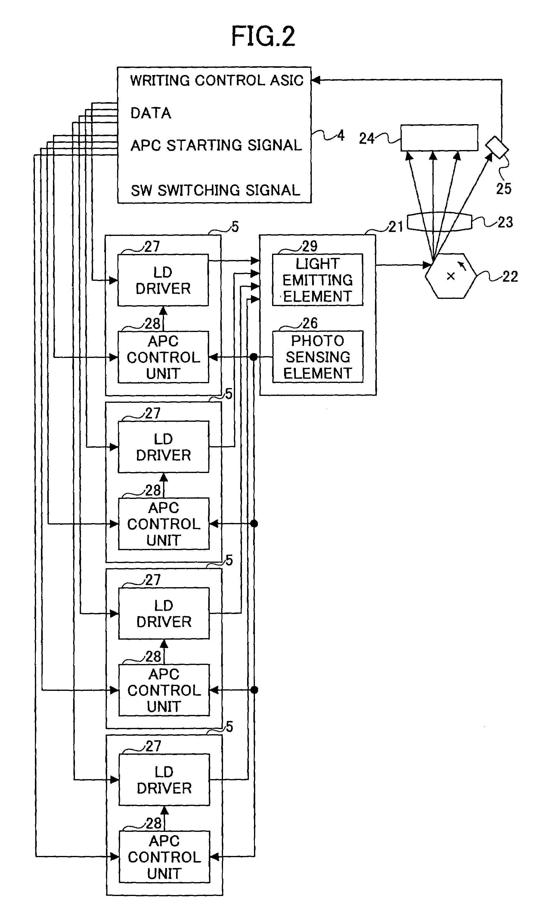
[0020]In the following descriptions of embodiments of the present invention, the image forming apparatus includes a photo sensing element for detecting laser beams emitted from a number of semiconductor lasers, a number of semiconductor laser control circuits each of which has an optical negative feed back loop for controlling a forward current of the corresponding semiconductor laser so as to make an electric signal obtained by converting the laser beam emitted from the corresponding semiconductor laser and detected by the photo sensing element equal to that of a light emitting level designating signal, and an APC (Auto Power Control) timing determination unit for determining the timing of the APC operations of the semiconductor laser control circuits.

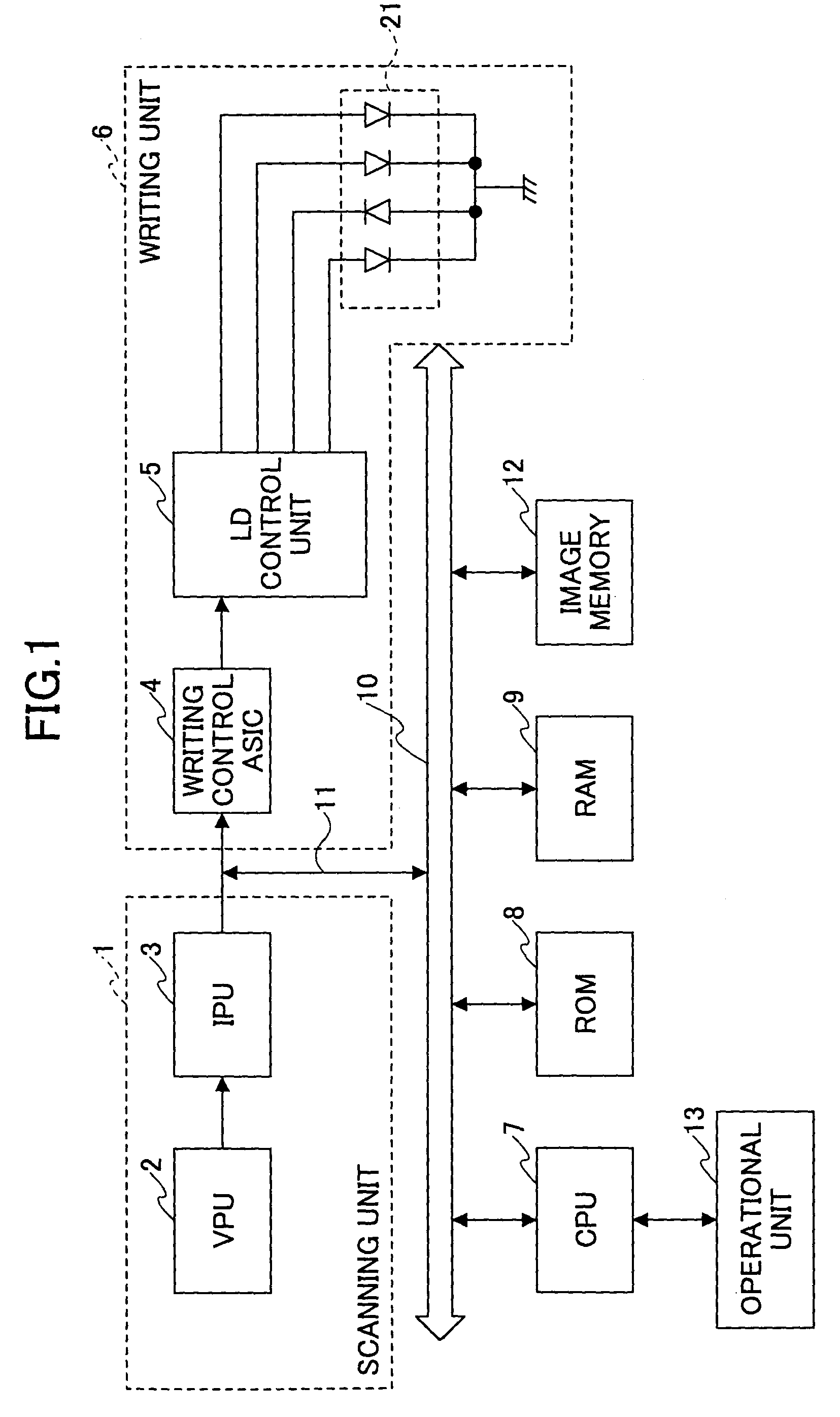
[0021]FIG. 1 is a block diagram showing a schematic configuration of an image forming apparatus according to an embo...


PUM


Abstract

An image forming apparatus is disclosed that is capable of making it simple to initialize a laser system thereof. The image forming apparatus includes a first photo detector that detects a part of a laser beam from each of the lasers and generates respective power adjustment signals for the lasers, a second photo detector that detects another part of the scanning laser beam of each of the lasers and generates a synchronization signal corresponding to each laser, and a power adjustment control unit that changes the output power of each of the lasers to a predetermined value. During the adjustment of output powers of the lasers, the power of a laser is monitored by using the synchronization signal. The power adjustment control unit turns on a laser for power adjustment, and turns off the laser when the scanning synchronization signal is detected twice to complete the power adjustment of the laser, and then starts power adjustment of the next laser.

Description

BACKGROUND OF THE INVENTION[0001]1. Field of the Invention[0002]The present invention relates to an optical writing device that includes a plurality of semiconductor lasers and is capable of adjusting amounts of the laser beams by using a photo sensing element, a controlling method thereof, and an image forming apparatus including the optical writing device.[0003]2. Description of the Related Art[0004]In the related art, a conventional image forming apparatus equipped with an optical writing device has a laser chip including a light emitting element and a photo sensing element (for example, a photo diode), and a semiconductor laser controller including an optical negative feed back loop for control of the laser chip. In order to increase printing speed and image quality of the image forming apparatus, a number of laser chips and the same number of laser controllers are provided in the image forming apparatus.[0005]To increase the printing speed and image quality, a laser chip is pro...

Claims


Application Information

Patent Timeline
Patent Type & Authority Patents(United States)
IPC IPC(8): H01J3/14H01J40/14H01J5/16B41J2/44B41J2/47G02B26/10G06K15/12H04N1/053H04N1/113H04N1/23
CPCB41J2/473G06K15/1214H04N1/053H04N1/1135H04N2201/04729H04N2201/0471H04N2201/04732H04N2201/04744
Inventor IKEDA, YOSHITO
Owner RICOH KK
Why Eureka
Try Eureka