Constrained-envelope digital communications transmitter and method therefor

a digital communication transmitter and envelope technology, applied in the field of electronic communication, can solve the problems of increasing the peak power needed to faithfully reproduce the filtered communication signal increasing the cost of power amplifiers, etc., to achieve the effect of improving the constrained envelope digital communication transmitter and method, reducing the peak-to-average power ratio, and increasing the predetermined bandwidth

Inactive Publication Date: 2006-02-14
INTERSIL INC
View PDF27 Cites 18 Cited by
  • Summary
  • Abstract
  • Description
  • Claims
  • Application Information

AI Technical Summary

Benefits of technology

[0007]It is an advantage of the present invention that an improved constrained-envelope digital communications transmitter and method are provided.
[0008]Another advantage is that a constrained-envelope digital communications transmitter and method are provided to generate a signal which, when combined with a modulated signal that exhibits a predetermined bandwidth, reduces peak-to-average power ratio without significantly increasing the predetermined bandwidth.
[0009]Another advantage is that a modulated signal which exhibits a desired bandwidth but undesirably large peak-to-average power ratio is adjusted to lessen the peak-to-average power ratio without significantly increasing bandwidth.
[0010]Another advantage of the present invention is that spectrally constrained corrective pulses are added to a modulated signal in a manner that minimizes growth in peak-to-average power ratio caused by the corrective pulses.
[0011]Another advantage of the present invention is that, in one embodiment, at least two constrained-envelope generators are coupled in series so that a downstream constrained-envelope generator can compensate for peak-to-average power ratio growth caused by an upstream constrained-envelope generator.
[0012]These and other advantages are realized in one form by an improved method of operating a digital communications transmitter to constrain envelope and spectral regrowth while processing a communication signal. The method calls for monitoring an overpeak-capable signal stream to identify occurrences of overpeak events by determining when a threshold is exceeded. When one of the overpeak events is identified, a corrective impulse configured to compensate for an amount by which the overpeak-capable signal stream is in excess of the threshold is generated. The corrective impulse is filtered to generate a shaped pulse having a leading portion and a trailing portion. The trailing portion of the shaped pulse is fed back so that, after the one of the overpeak events, the overpeak-capable signal stream is responsive to the trailing portion of the shaped pulse and the communication signal. A constrained-envelope signal stream is produced in response to the communication signal and the corrective impulse.

Problems solved by technology

Unfortunately, as α is reduced, the peak power needed to faithfully reproduce the filtered, spectrally constrained signal increases.
A similar dilemma occurs in connection with applications where many channels are combined into a composite signal prior to amplification, regardless of modulation type and independent of pulse shaping.
A communication signal with a high peak-to-average power ratio is undesirable because such a signal requires the use of a high quality linear amplifier capable of amplifying the greatest signal peaks.
As peak-to-average power ratio increases, power amplifier costs likewise increase to accommodate increasingly high and increasingly infrequent peaking events.
The problem of reducing peak-to-average power ratios in communication signals is difficult to solve.
However, this is a highly undesirable solution because it leads to dramatic spectral regrowth.
A moderately better, but still undesirable, technique uses a spectrally inefficient pulse shape in the pulse-shaping filter to limit the greatest signal peaks.
But, this technique still suffers from an undesirable amount of spectral regrowth.
Other complex techniques require such extensive processing capabilities that they are not practical in connection with high-throughput or continuous, rather than burst, transmission applications, i.e., those greater than 0.5 Mbps, such as the transmission of high-speed video data through a single channel or other data through multiple channels in parallel.
While the technique of U.S. Pat. No. 6,104,761 produces adequate results for many applications, it has been discovered that the corrective pulses themselves may combine in certain situations in a manner that leads to an undesired signal peak, even though an acceptable signal level would have been present had the corrective pulses not been applied.
As a result, while significant peak-to-average power reductions were observed, such peak-to-average power reductions were not as great as they could have been.

Method used


Image

  • Constrained-envelope digital communications transmitter and method therefor
  • Constrained-envelope digital communications transmitter and method therefor
  • Constrained-envelope digital communications transmitter and method therefor

Examples


first embodiment

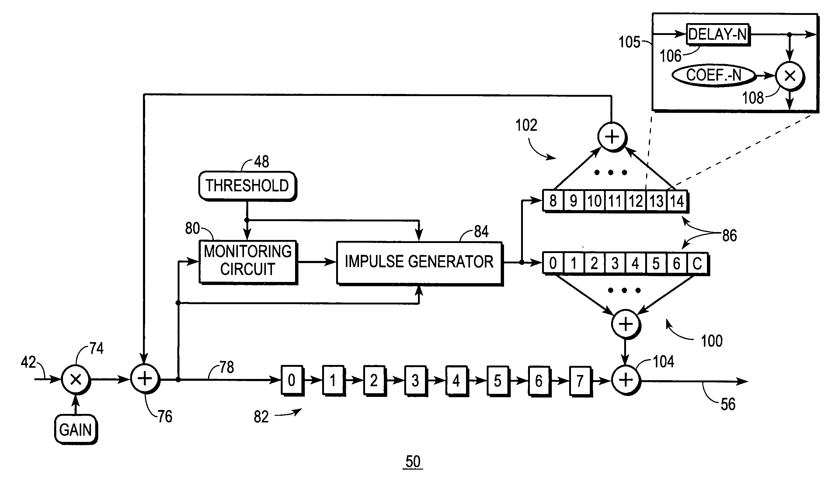
[0042]FIG. 5 shows a block diagram of a constrained-envelope generator 50 usable in transmitter 10. The FIG. 5 embodiment of constrained-envelope generator 50 may be used in the position of any one of the constrained-envelope generators 50 depicted in FIG. 1.

[0043]Constrained-envelope generator 50 receives a spectrally-constrained communication signal 42 at an input of an optional scaling stage 74. At scaling stage 74, a gain factor may be applied as needed by the application. For example, in some applications power management techniques may require communication devices located closer together to operate at lower power levels than father-apart communication devices so long as an adequate signal-to-noise ratio may be delivered at the lower power level. Such power management techniques may be applied at scaling stage 74 if not applied elsewhere in transmitter 10 (FIG. 1).

[0044]After scaling, the spectrally constrained signal stream is applied to a combining circuit 76. Combining circ...

second embodiment

[0057]FIG. 8 shows a block diagram of a constrained-envelope generator 50. The embodiment of constrained-envelope generator 50 depicted in FIG. 8 performs an equivalent function to that discussed above in connection with FIG. 5, but incorporates the function of pulse shaping filter 40 (FIG. 1) therein. The FIG. 8 embodiment may be used for the upstream-most one of constrained-envelope generators 50 or as a sole constrained-envelope generator 50 in a transmitter 10 (FIG. 1).

[0058]Like the FIG. 5 embodiment, constrained-envelope generator 50 configured in accordance with the FIG. 8 embodiment includes monitoring circuit 80 and impulse generator 84 which are responsive to overpeak-capable signal stream 78 and to threshold 48 and which operate in the manner discussed above to identify overpeak events 52 and to generate corrective impulses 54. However, shaped pulse 88 is generated in combination with pulse shaping performed on spectrally-unconstrained communication signal 14. Like the FI...


PUM


Abstract

A constrained-envelope digital communications transmitter (10) places constraints on the envelope of a spectrally constrained, digitally modulated communication signal (42) to lower peak-to-average power ratio without allowing significant spectral regrowth. A communication signal (14,42) is applied to a plurality of cascade-coupled constrained-envelope generators (50). Each constrained-envelope generator (50) detects overpeak events (52) and configures corrective impulses (54) for the overpeak events (52). The corrective impulses (54) are filtered into shaped pulses (88) that exhibit a constrained spectrum and combine with the communication signal (14, 42) to reduce an unwanted signal peak. Trailing portions (92) of the shaped pulses (88) are fed-back and combined with the communication signal (14,42) so that future overpeak events (52) are identified after compensation is made for the influence of the trailing portions (92) of any recently past shaped pulses (88) on the communication signal (14,42).

Description

TECHNICAL FIELD OF THE INVENTION[0001]The present invention relates generally to the field of electronic communications. More specifically, the present invention relates to the field of constrained-envelope digital transmitters.BACKGROUND OF THE INVENTION[0002]Many prior art digital communication systems use a pulse-shaping filter, and often some form of Nyquist-type filtration, such as Nyquist, root-Nyquist, raised cosine-rolloff, etc., to shape and spread the information conveyed in each unit interval of modulated data over many unit intervals in a manner that dramatically reduces the spectrum required to transmit the information but permits efficient recovery of the information without significant intersymbol interference. Lower alpha (α) values for the pulse-shaping filter are more desirable because lower values lead to reduced spectrum requirements. Unfortunately, as α is reduced, the peak power needed to faithfully reproduce the filtered, spectrally constrained signal increase...

Claims


Application Information

Patent Timeline
Patent Type & Authority Patents(United States)
IPC IPC(8): H04L27/04H04L25/03H04L27/26H04L27/34
CPCH04L25/03834H04L27/3411H04L27/2614
Inventor SHEARER, LLL, DANIEL DAVIDSON MACFARLANE
Owner INTERSIL INC
Why Eureka
Try Eureka