Dispersion-controlled optical fiber

Active Publication Date: 2006-02-14
SAMSUNG ELECTRONICS CO LTD
View PDF11 Cites 235 Cited by
  • Summary
  • Abstract
  • Description
  • Claims
  • Application Information

AI Technical Summary

Benefits of technology

[0015]Accordingly, the present invention has been made to solve the above-mentioned problems occurring in the prior art and provides a dispersion-controlled

Problems solved by technology

However, the dispersion-controlled optical fiber of this type has drawbacks in that its bending loss tends to be high as it has a region with a highly depressed refractive index in its cladding.
Furthermore, it is inappropriate for broad-band transmission, and the loss and dispersion characteristics are poor in higher and lower wavelength ranges.
As such, if the dimension of its base material forms a large aperture, a problem will arise as relatively large stresses are applied to the core part at the time of drawing it.
This means that it is difficult for various optical characteristics to have constant values in accordance with drawing temperatures.
Also, it is not easy to manufacture a dispersion-controlled optical fiber if it has relatively sensitive characteristics when compared to a common single-mode optical fiber.
In addition, the existing dispersion-controlled optical fibers are adapted to be used in the wavelength range of about 1530˜1565 nm by setting the zero dispersion wavelength around 1530 nm, wherein the optical fibers have a dispersion characteristic of not more than 5 ps/nm·km at 1550 nm and their diameters range between 8˜9 μm, thus being problematic in that they are inappropriate for communication exceeding the 10 Gbps level.
As explained above, dispersion-controlled optical fibers in the prior art have

Method used


Image

  • Dispersion-controlled optical fiber
  • Dispersion-controlled optical fiber
  • Dispersion-controlled optical fiber

Examples


Embodiment Construction

[0023]Hereinafter, preferred embodiments of the present invention will be described in detail with reference to the accompanying drawings. For the purposes of clarity and simplicity, a detailed description of known functions and configurations incorporated herein will be omitted as it may make the subject matter of the present invention unclear.

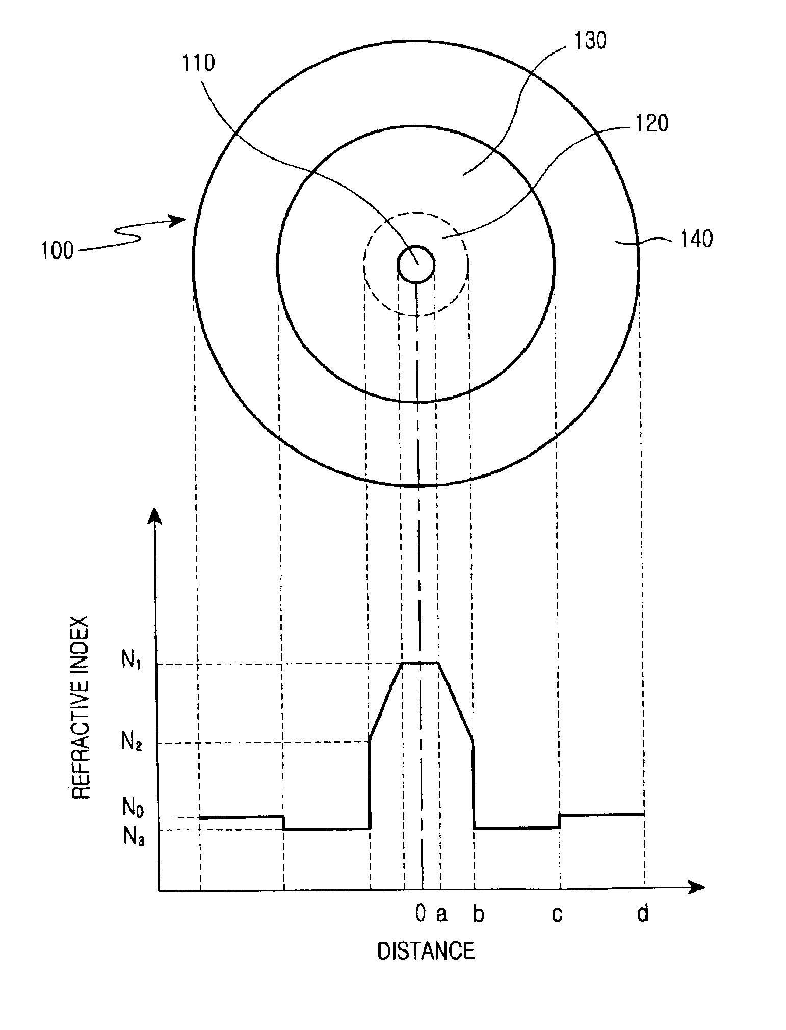
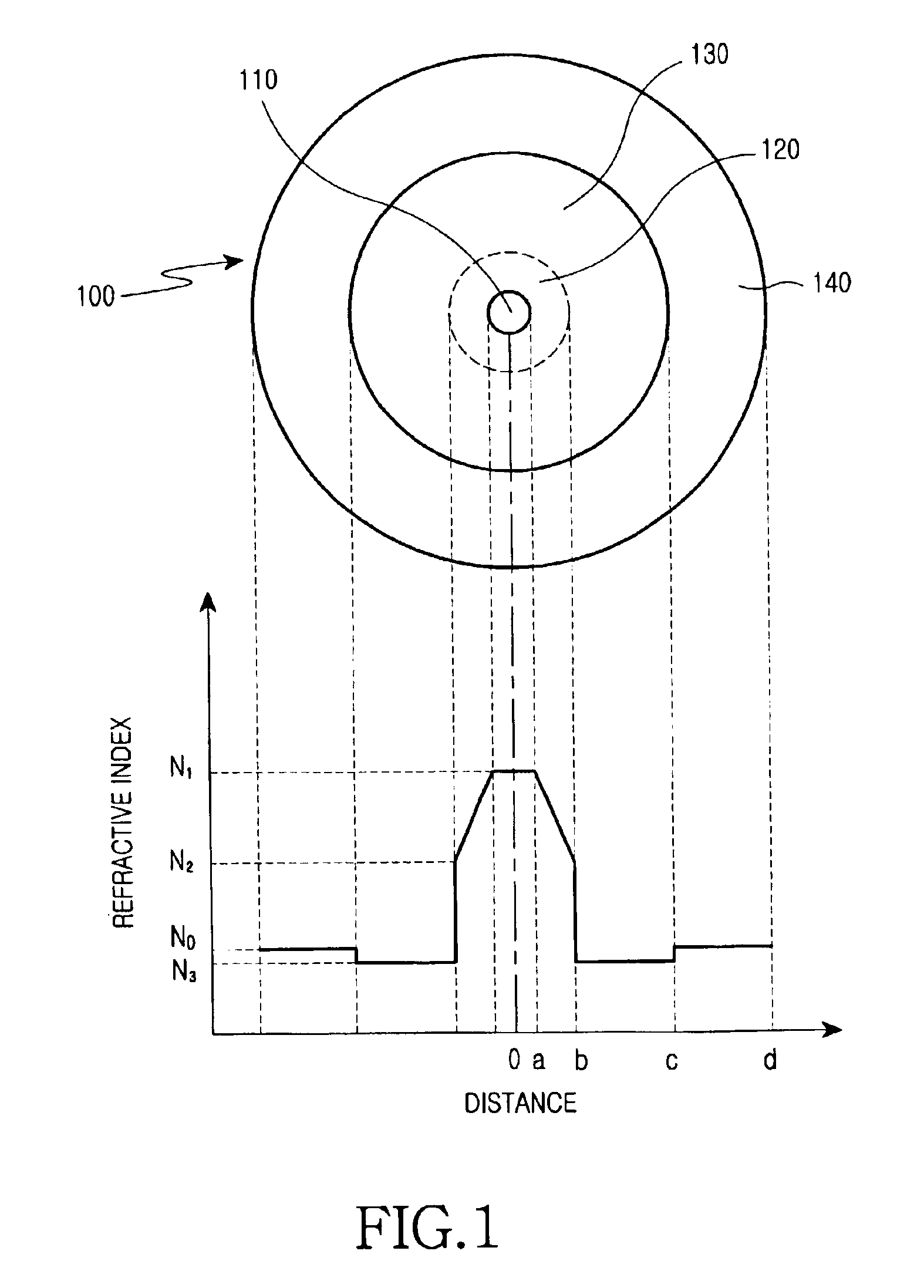
[0024]FIG. 1 shows the construction and distribution of the refractive indices of a dispersion-controlled optical fiber in accordance with a preferred embodiment of the present invention. As shown in FIG. 1, the dispersion-controlled optical fiber 100 consists of a center core 110, an upper core 120, a minutely depressed refractive index region 130, and a cladding 140.

[0025]The center core 110 consists of silica and has a radius, a. In the embodiment, the center core 110 is doped with a predetermined amount of germanium for tuning its refractive index to N1.

[0026]The upper core 120 has an internal radius of a and an external radius of b, and ...


PUM


Abstract

Disclosed is an optical fiber comprising a center core which forms a passageway for transmitting optical signals and has a refractive index N1, and a cladding which encloses the center core and has a refractive index N0. The optical fiber further comprises an upper core, which has a distribution of refractive indices increased starting from a refractive index N2 (>N0) at its outer circumference to the refractive index N1 at its internal circumference, and a minutely depressed refractive index region, which is interposed between said upper core and cladding and has a refractive index N3. The refractive index N3 is lower than the refractive index N0.

Description

CLAIM OF PRIORITY[0001]This application claims priority to an application entitled “Dispersion-controlled optical fiber” filed with the Korean Intellectual Property Office on Apr. 3, 2002 and assigned Serial No. 2002-18162, the contents of which are hereby incorporated by reference.BACKGROUND OF THE INVENTION[0002]1. Field of the Invention[0003]The present invention relates to an optical fiber and, more particularly, to a broad band dispersion-controlled optical fiber.[0004]2. Description of the Related Art[0005]As one skilled in the art can readily appreciate, an optical fiber consists of a core and a cladding, wherein the refractive index of the core is higher than that of the cladding. Common known methods for manufacturing the base material of an optical fiber includes the Modified-Chemical-Vapor Deposition (MCVD) method, Vapor-phase Axial Deposition (VAD) method, Outside Vapor-phase Deposition(OVD) method, Plasma-Chemical-Vapor Deposition(PCVD) method and the like.[0006]For ach...

Claims


Application Information

Patent Timeline
IPC IPC(8): G02B6/02G02B6/00G02B6/036
CPCG02B6/02266G02B6/03627G02B6/02009G02B6/0228G02B6/02
Inventor JANG, YUN-GEUNDO, MUN-HYUNCHOI, SUNG-WOOKHAN, JU-CHANGCHO, JEONG-SIKYANG, JIN-SEONG
Owner SAMSUNG ELECTRONICS CO LTD
Why Eureka
Try Eureka