Fluid dispenser having a housing and flexible inner bladder

a technology of flexible inner bladder and dispenser, which is applied in the field of dispensers, can solve the problems of vapor loss, nozzles and/or valves used in typical prior art dispensers often being incapable of maintaining the dispenser in a hermetically sealed condition, and vapor loss

Inactive Publication Date: 2006-02-21
DR PY INST LLC
View PDF129 Cites 110 Cited by
  • Summary
  • Abstract
  • Description
  • Claims
  • Application Information

AI Technical Summary

Benefits of technology

[0010]In accordance with a first aspect the present invention is directed to a dispenser for dispensing a fluid. The dispenser comprises a rigid housing, and a flexible bladder mounted within the housing and defining an interior chamber within the flexible bladder, and a fluid-receiving chamber between the flexible bladder and the rigid housing. The dispenser further comprises means for creating a first pressure within the fluid-receiving chamber greater than a second pressure within the interior chamber of the bladder to thereby prevent the ingress of gases or vapors into the fluid-receiving chamber. In a currently preferred embodiment of the present invention, the means for creating the pressure differential is formed by a resilient material of the bladder that flexes the bladder outwardly toward an expanded condition, and thereby creates the first pressure within the fluid-receiving chamber greater than the second pressure in the interior chamber of the bladder. Preferably, the resilient bladder is molded in the expanded condition, and therefore the resilient bladder will inherently tend to force itself into the expanded condition and thereby create the desired pressure differential between the fluid-receiving chamber and the interior chamber of the bladder.

Problems solved by technology

One of the drawbacks associated with typical prior art fluid dispensers is that the fluid chamber(s) are not maintained in a substantially airless condition throughout the storage, shelf life and / or usage of the dispenser.
For example, the nozzles and / or valves used in typical prior art dispensers frequently are incapable of maintaining the dispenser in a hermetically sealed condition.
In addition, such nozzles and / or valves frequently allow vapor loss therethrough either during the storage, shelf life or usage of the dispensers.
Another drawback associated with prior art dispensers is that the materials of construction may undergo creep that, in turn, causes seals formed within the dispensers to leak.
As a result, the dispensers are frequently subjected to substantial differential thermal expansion and / or contraction that, in turn, cause the materials of construction to undergo creep.
The seals and other components of such prior art dispensers typically are not designed to address such creep, and as a result, the dispensers develop leaks or otherwise allow air ingress and / or vapor loss when subjected to such long periods of storage or varying atmospheric conditions.
For example, some polyethylene dispensers have been known to lose between about 10% to 25% of the weight of their contents during storage.
Such weight loss is believed to be due to vapor loss from the medicament or other fluid-containing chambers through the polyethylene walls of the dispensers and / or through leaks otherwise created in the seals or other structural interfaces of the containers.
Vapor loss and / or air ingress is particularly problematic for dispensers containing medicaments, such as pharmaceutical preparations or vaccines, because they tend to dilute each predetermined dosage of the medicament dispensed from the container, and / or cause the dispenser to dispense inconsistent concentrations of medicament from one dose to the next.
Yet another disadvantage associated with prior art dispensers is that because they cannot reliably maintain the medicament or other substance contained therein in an airtight condition, they cannot be used for either multiple dose applications or preservative-free formulations.
The use of single dose dispensers can be substantially more expensive than multiple dose dispensers.
In addition, the preservatives used in many medicaments, such as pharmaceutical preparations and vaccines, can cause adverse reactions in patients and / or dilute the effect of the medicament on the patient.
Another drawback of prior art dispensers is that the ullage or “dead space” inherent in such dispensers allows sediment build-up.
Another drawback associated with many prior art dispensers is that they can only dispense the medicament or other substance contained therein in an upright or other single orientation.
This drawback prevents such dispensers from being used effectively in other orientations, such as upside down.
In addition, because such dispensers do not maintain the medicament or other substance contained therein in an airless condition, they cannot be used in low gravity environments, such as outer space.

Method used


Image

  • Fluid dispenser having a housing and flexible inner bladder
  • Fluid dispenser having a housing and flexible inner bladder
  • Fluid dispenser having a housing and flexible inner bladder

Examples


Embodiment Construction

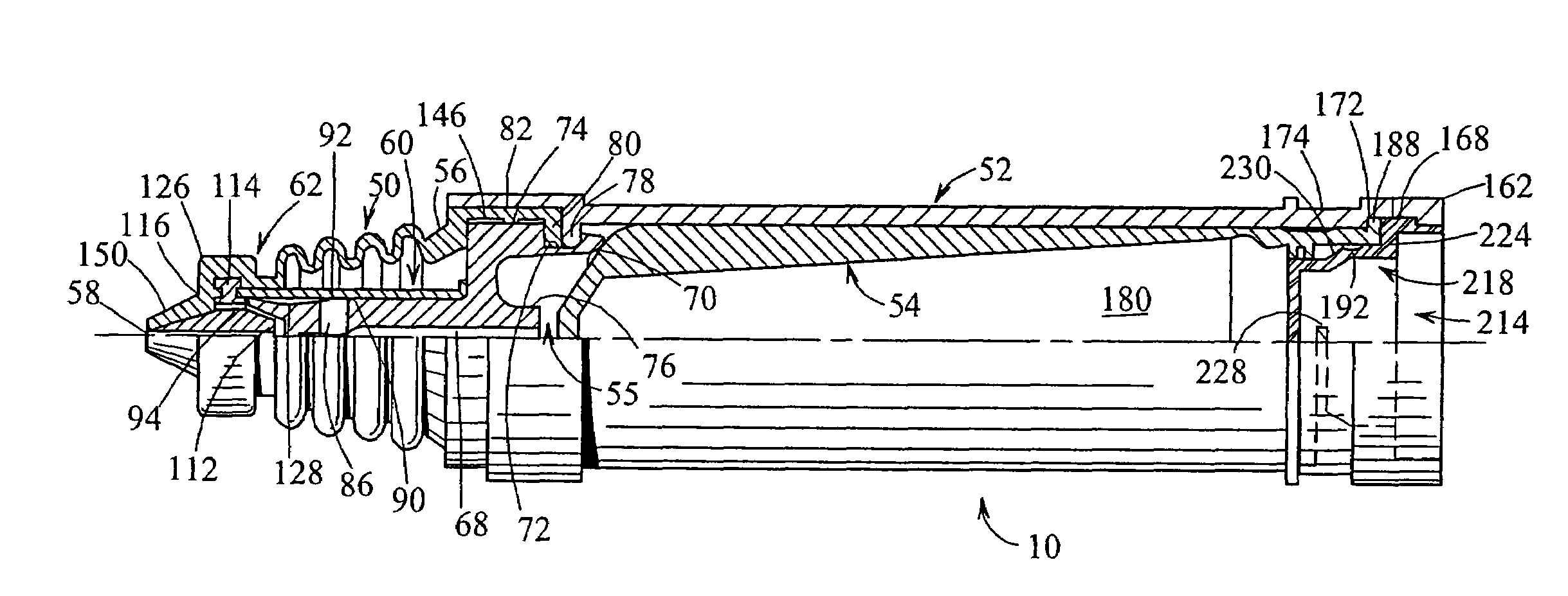
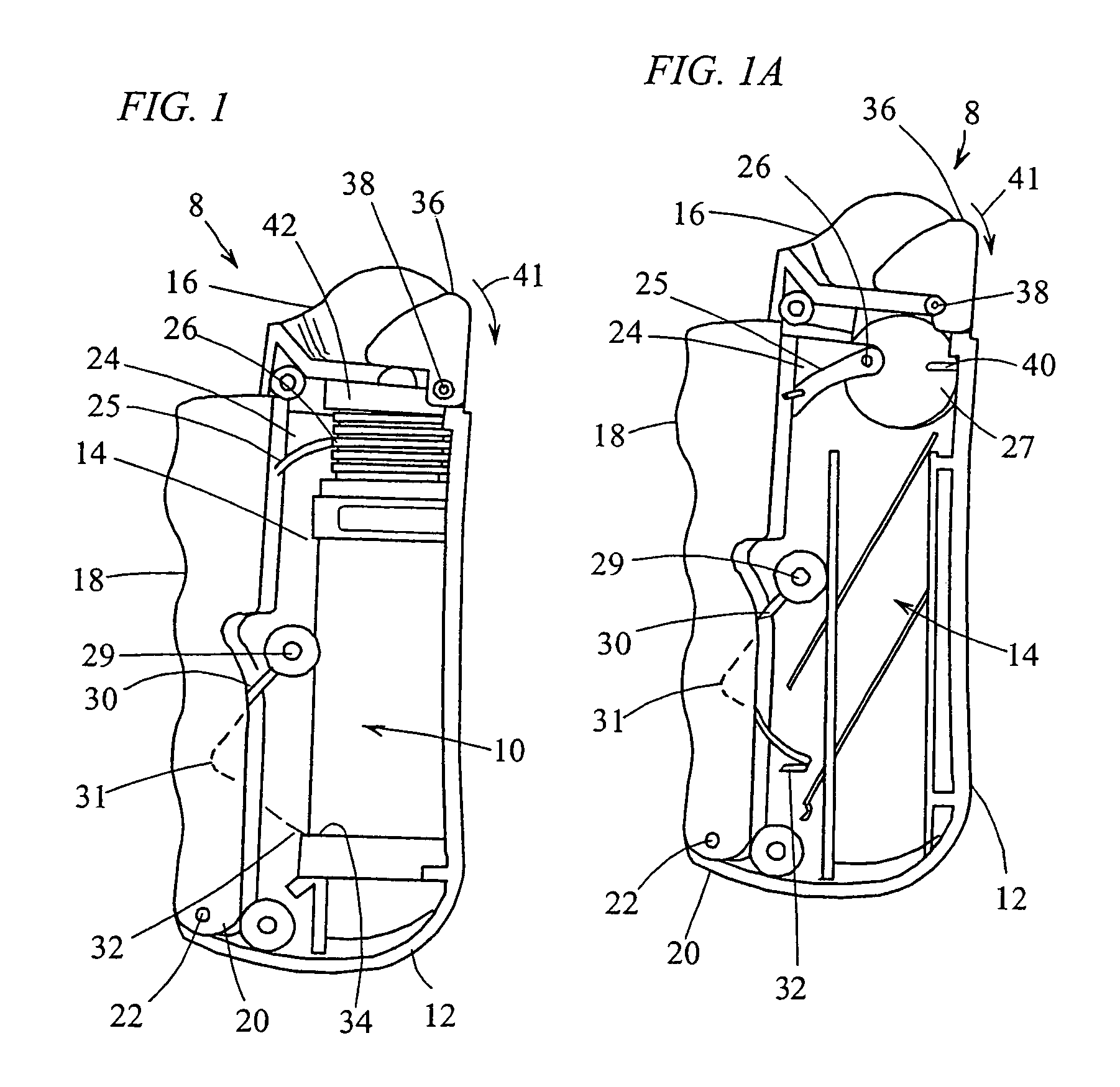
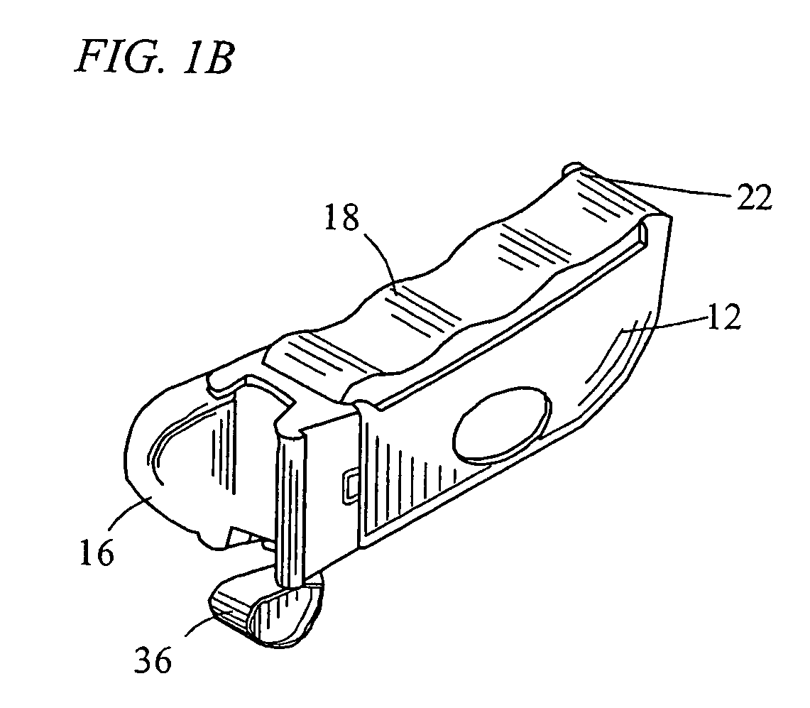
[0065]In FIG. 1, there is shown an ocular treatment apparatus 8 that may be used in conjunction with a dispenser, shown generally at 10, in accordance with the present disclosure. As seen in FIGS. 1 and 1A, the treatment apparatus S comprises a housing 12 that may be generally U-shaped in cross section, and defines an interior cavity 14 and an eye cover 16. A trigger 18 is pivotally connected at one end 20 to the housing 12 via a hinge 22, and includes at the other end an arm portion 24 defining a slot 25. As shown best in FIG. 1A, a pin 26 of a wheel 27 is fixedly secured within the slot 25, and the wheel 27 is rotatably mounted on the interior wall of the housing 12. As best seen in FIG. 1, the trigger 18 is elongated and comprises finger grooves 28 for a comfortable fit with, e.g., a patient's hand. An approximately L-shaped spring arm 30 is fixedly secured at one end to a post 29 projecting inwardly from the interior wall of the housing 12, and the spring arm defines a knee or b...


PUM


Abstract

A dispenser for dispensing a fluid includes a rigid vial that has a main fluid chamber containing a fluid, and a pump assembly that is in fluid communication with the main fluid chamber and is configured to dispense a predetermined quantity of fluid from the main fluid chamber. A flexible bladder is provided which is located within the main fluid chamber and is configured to expand to fill the ullage created within the main fluid chamber during dispensing of fluid by the pump assembly. The resilient bladder tends to force itself outwardly toward the rigid vial and, in turn, increases the pressure within the main fluid chamber in comparison to the interior of the bladder to thereby prevent the ingress of air or vapors through the bladder or otherwise into the main fluid chamber.

Description

CROSS-REFERENCE TO RELATED APPLICATIONS[0001]This patent application is a continuation of U.S. patent application Ser. No. 10 / 001,745, filed Oct. 23, 2001, now U.S. Pat. No. 6,761,286, entitled “Fluid Dispenser Having a Housing and Flexible Inner Bladder”, which claims the benefit of U.S. Provisional Application Ser. No. 60 / 242,595, filed Oct. 23, 2000, entitled “Fluid Dispenser Having A Rigid Vial And Flexible Inner Bladder”, and U.S. Provisional Application Ser. No. 60 / 242,974, filed Oct. 24, 2000, entitled “Fluid Dispenser Having A Rigid Vial And Flexible Inner Bladder”, all of which are hereby incorporated by reference as part of the present disclosure.FIELD OF THE INVENTION[0002]The present disclosure relates generally to dispensers for dispensing fluids or other substances and, more particularly, to a dispenser having a rigid vial, a flexible bladder disposed within the rigid vial and defining a chamber between the flexible bladder and rigid vial for receiving therein a fluid ...

Claims


Application Information

Patent Timeline
Patent Type & Authority Patents(United States)
IPC IPC(8): B67D5/42B67D7/06A61F9/00B05B11/00B65D81/24B65D83/00B65D83/76B67D7/58B67D7/60B67D7/84
CPCA61F9/0008B05B11/0043B05B11/0072B05B11/0097B05B11/3004B65D83/0055B05B11/3077B05B11/3092B05B11/3094B65D81/245B05B11/3074B05B11/1004B05B11/026B05B11/1074B05B11/1077B05B11/1092B05B11/1094B65D83/00
Inventor PY, DANIELTING, JOSEPH M.
Owner DR PY INST LLC
Why Eureka
Try Eureka