Such traditional backlights are characterized by poor brightness uniformity and by small
aspect ratio.
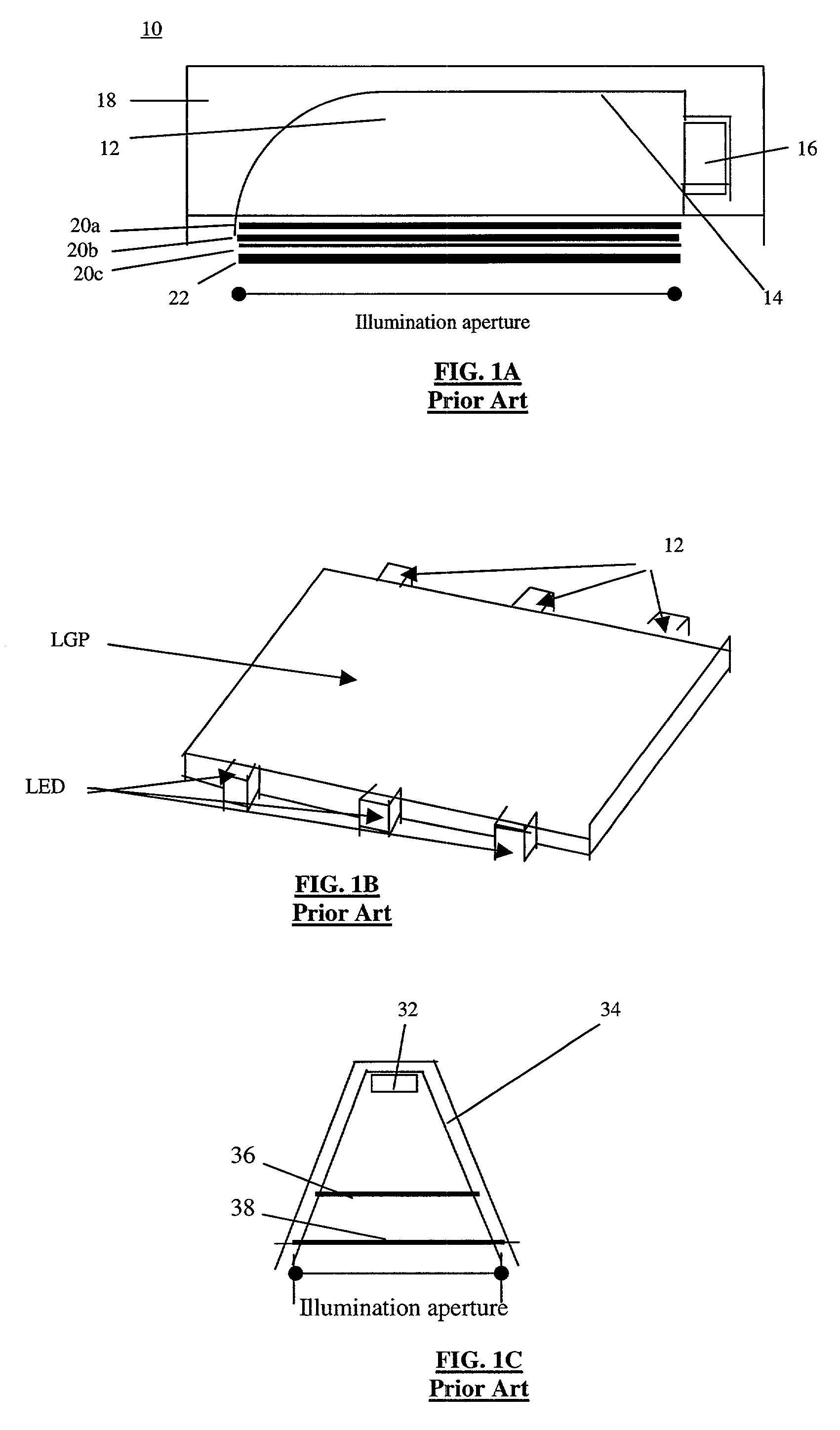
The use of multiple LEDs is dictated by a need to improve the luminance uniformity, which is poor (remains below an acceptable value) with one LED in existing devices.
While more compact than the previously mentioned devices, the device of FIG. 1A still suffers from several practical problems.
First, the device of FIG. 1A is still very large in all dimensions with respect to the size of the illumination aperture and has the additional
disadvantage of being energetically inefficient.
In practice, the requirement of uniform illumination with cavital design is difficult to achieve, in particular for larger and thinner configurations, i.e., larger
aspect ratio designs.
Indeed, the performance of such a device imposes two conflicting requirements on AR.
As a result, prior art devices are bulky in terms of
depth dimension and / or cannot assure an acceptable uniformity for larger displays.
While these performance criteria may be suitable for some LCD applications, they are not sufficient for applications using multi-
colored LED sources, as described below, in which a uniformity between the illumination colors of 1.05:1 is required in order to prevent perceivable color shifts.
In fact, only an upper surface of such filled cavity acts as a
light guide, but its ratio to the total surface area of the cavity is too small to have any significant positive effect.
As a result, such systems fail to appreciably improve the backlight luminance efficiency and achievable AR.
However as realized herein, several practical problems inherent to such a
system are compounded in the case of small-aperture LGP-based backlights.
A first of these practical problems include the fact that a relatively thick planar LGP, with 1<AR<10, suffers from elevated
light flux losses, since, with existing extraction means, a large fraction of the LED-injected flux inevitably reaches the opposite edge of the LGP and is coupled out on the proximal outer reflector; it is then coupled again into the LGP, travels in a reverse direction and eventually ends up on the LED, where it is totally or partially absorbed.
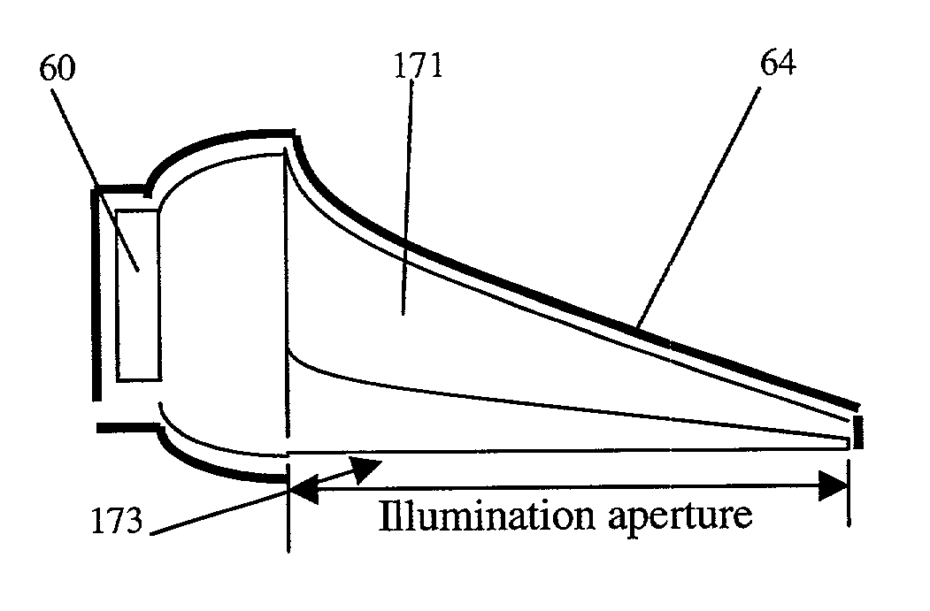
However, these linear wedge shaped devices inherently produce a significantly non-uniform luminance, this non-uniformity growing with the LGP's length.
This one-dimensional nonlinear wedge is not designed to produce uniform luminance independently.
These patents fail to teach any practical solutions and in fact, the expanding convex wedges qualitatively depicted therein necessarily suffer from augmented non-uniformity as compared to linear wedges.
Further, the attempt to analyze the problem using general adiabatic invariant cannot produce any meaningful solution since one has to consider the exact convolutions of Fresnel equations in three dimensional domain with complex boundary conditions, imposed by the LGP shape, and backward propagating
residual flux.
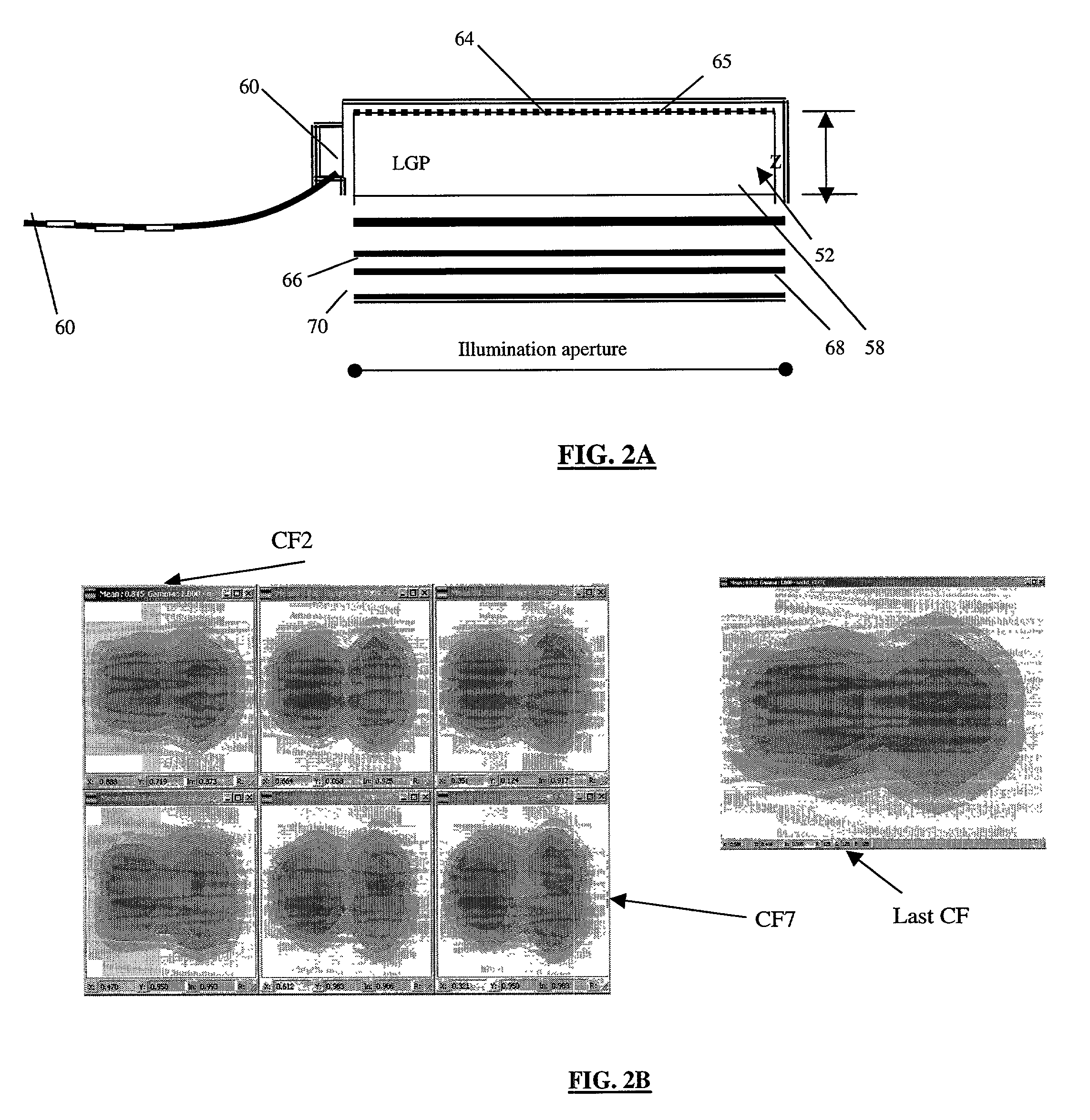
A second practical problem resides in the fact that in order to attain high illumination uniformity, light extraction from the LGP's internal flux should be nonuniform.
Indeed, flux density inside the LGP having some extractor means is generally not uniform and diminishes gradually with increasing distance from the light source.
In order to overcome this phenomenon, the extractor elements in prior art devices are distributed non-uniformly, being more sparse near the lamp and more crowded near the opposite edge.
A third practical problem related to the fact that an efficient
coupling architecture is required to take the light emitted from a LED source and inject it efficiently into a thin lightguide.
LEDs with conventional primary
optics (lens-like or flat shaped
epoxy encapsulants in direct optical contact with the LED emitter and / or reflector cup) suffer from very significant losses due to Fresnel retroreflection of initially emitted flux.
Similar losses also occur for LEDs with a cup-shaped or cup reflector surrounding the emitter.
Most of the thus retroreflected flux is absorbed in the LED, causing output losses and eventual elevation of LED
chip temperature, which reduces the LED's
luminous efficacy.
This is a problem as current LED backlights only have optical efficiencies in the range of 50–75% and uniformity typically in the 1.3–1.4:1 range.
Any backlight that uses a white lamp as the light source, including the above-mentioned white LED, has an important drawback, namely that the spectrum of the emitted light is fixed and is determined almost solely by that of the lamp.
In the aforementioned conventional type of backlights such a control is very difficult, in that it can only be accomplished by carefully selecting the lamp or by interposing suitable correction filters.
In other words, the display efficiency is considerably reduced.
A second drawback is that color-filter-array type LCDs has relatively high cost of manufacturing due to the intricacies of the manufacturing process.
A third drawback relates to the fact that, for a given pixel resolution, the basic LCD resolution must be at least three times higher (per unit area).
This last drawback has become a particular liability in the case of small-aperture display devices, especially as they simultaneously strive for higher resolution, which correspondingly puts a premium on pixel real estate, while requiring even more pixels in the shrinking space.
According to prior art, LEDs cannot, however, be practically used to illuminate the edge of a LGP to serve as a backlight, because each is, in effect, a
point source of light (as opposed to the elongated format of the light emitted by CCFLs), which causes the resulting pattern of
light flux emitted from the face of a typical LGP to be highly non-uniform.
Further disadvantages of such prior-art devices are that the LEDs themselves have a non-uniform
radiation pattern, which further contributes to the non-uniformity of the backlight, and that the three LED sources must still be placed at some mutual distances, which causes non-uniformity in the
hue of white over the display, as discussed above.
This device, however, suffers from the disadvantages already discussed above.

