Method and device for setting the focal spot position of an X-ray tube by regulation

a technology of x-ray tubes and focal spots, which is applied in the direction of x-ray tubes, radiation beam directing means, diagnostics, etc., can solve the problems of inducible capacity and disturbance, source of errors,

Inactive Publication Date: 2006-02-21
SIEMENS HEALTHCARE GMBH
View PDF2 Cites 33 Cited by
  • Summary
  • Abstract
  • Description
  • Claims
  • Application Information

AI Technical Summary

Benefits of technology

[0011]An object of the invention is to provide a device and a method with the focal spot position set in an X-ray tube so that not only the foreseeable bu

Problems solved by technology

The voltage dividers for tapping the signal proportional to the X-ray voltage represent stray capacitances, which vary over time and are susceptible to disturbances.
The electrical connection between the deflection control and the tapping of the high voltage signal also possesses stray capacitances and disturbance inductivities as possible sources of errors.
Last bu

Method used


Image

  • Method and device for setting the focal spot position of an X-ray tube by regulation
  • Method and device for setting the focal spot position of an X-ray tube by regulation
  • Method and device for setting the focal spot position of an X-ray tube by regulation

Examples


Embodiment Construction

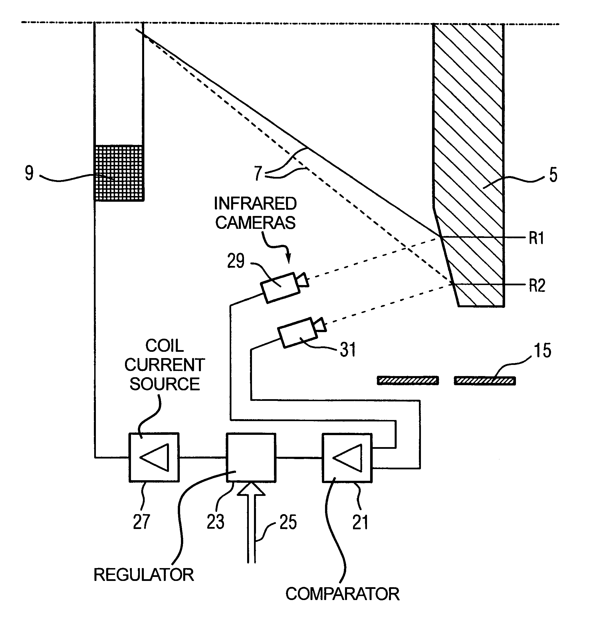
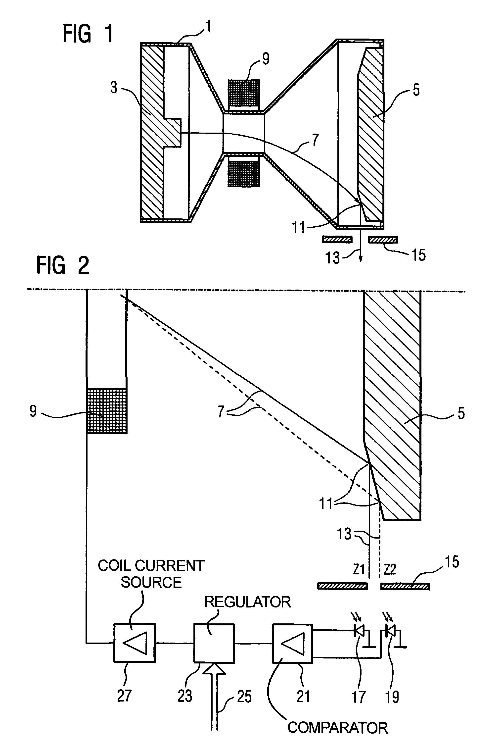
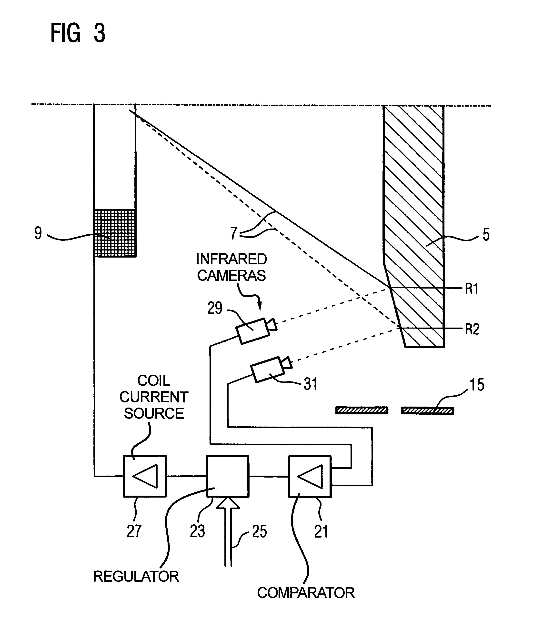
[0023]FIG. 1 schematically shows an arrangement for the regulation of the focal spot position of an X-ray tube 1. In the X-ray tube 1, electrons are emitted from the cathode 3 and are accelerated to the anode 5 due to the applied X-ray voltage. The electrons leave the cathode 3 already focused and thus form an electron beam 7. The electron beam 7 is deflected by deflection coils 9 and thus has a curved optical path. Although deflection coils 9 are common for deflecting the electron beam 7, deflection plates or other devices can also be used to create electromagnetic fields.

[0024]The electron beam 7 strikes the anode 5 in the focal spot 11. The position of the focal spot 11 depends on the strength of the deflection field created by the deflection coils 9 as well as the kinetic energy of the electrons caused by the X-ray voltage. The width of the electron beam 7 can be influenced by additional measures for focusing. When the anode 5 is struck, the electrons generate characteristic X-r...


PUM


Abstract

In a method and a device for setting the focal spot position of an X-ray tube the focal spot position is regulated as a controlled variable by a closed loop regulation circuit. A deflector deflects the electron beam of the X-ray tube depending on a deflection signal, a deflection closed loop regulator generates the deflection signal depending on a focal spot position signal. A measurement arrangement measures a focal spot position signal. The deflector, the deflection closed loop regulator and the measurement arrangement form a closed loop regulation circuit with the focal spot position as the controlled variable and with the deflection signal as the control parameter.

Description

BACKGROUND OF THE INVENTION[0001]1. Field of the Invention[0002]The present invention concerns a device and a process for setting the focal spot position of the electron beam on the anode of an X-ray tube.[0003]2. Description of the Prior Art[0004]X-ray tubes are used in X-ray devices in order to generate X-radiation. Electrons from a cathode are accelerated in the X-ray tube through an electric field at the X-ray voltage to an anode. When they strike the anode, the electrons create characteristic X-radiation as a result of their kinetic energy. The direction and shape of the X-rays that are generated are determined by the quality and orientation of the surface of the anode as well as by the direction and focal spot position of the electron beam when it strikes the anode. In order to create a bundled and intensive X-ray beam in the desired direction, the electron beam is focused and directed at a specific point on the anode surface.[0005]While electric fields are also used to focus ...

Claims


Application Information

Patent Timeline
IPC IPC(8): A61B6/08H01J35/14H05G1/52
CPCH05G1/52H01J35/14H01J35/153
Inventor DEURINGER, JOSEFGURTNER, ROLFZEISKE, KARSTEN
Owner SIEMENS HEALTHCARE GMBH
Why Eureka
Try Eureka