Method of controlling electrical rotating machines connected to a common shaft

a technology of electric rotating machines and common shafts, applied in the direction of electric generator control, motor/generator/converter stoppers, dynamo-electric converter control, etc., can solve the problem of large torque increase, achieve the effect of avoiding “power hogging” and maximizing system efficiency

Inactive Publication Date: 2006-02-21
UNITED TECH CORP
View PDF9 Cites 44 Cited by
  • Summary
  • Abstract
  • Description
  • Claims
  • Application Information

AI Technical Summary

Benefits of technology

[0014]The invention has the advantage that a powertrain having multiple generators is able to match the loads between generators evenly, avoiding “power hogging” that would endanger the gearing and the electrical equipment in an overloaded sub-powertrain.
[0015]The invention has the advantage that the control method provides variable speed operation when wind or water flow is sufficient to produce power, and provides for variable speed gust mitigation when peak power output of the turbine is reached.
[0016]The invention has the advantage that for a DGD system having five or more generators the control method provides for very close load sharing between generators, and provides incremental engagement of generators in a way that maximizes system efficiency.

Problems solved by technology

This increase in power is often accompanied by a reduction in rotational velocity of the power-input shaft, resulting in a large increase in torque.

Method used


Image

  • Method of controlling electrical rotating machines connected to a common shaft
  • Method of controlling electrical rotating machines connected to a common shaft
  • Method of controlling electrical rotating machines connected to a common shaft

Examples


Embodiment Construction

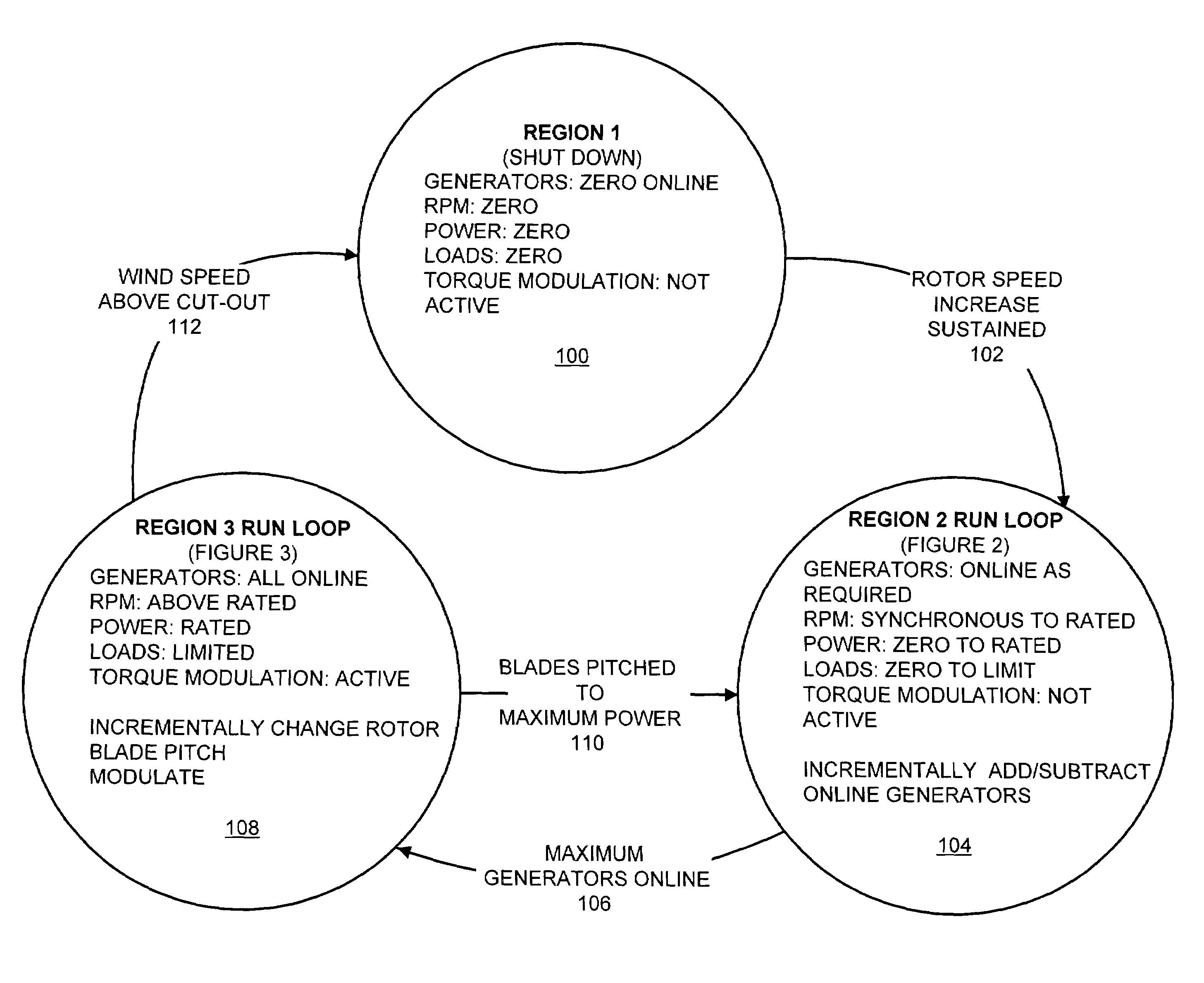
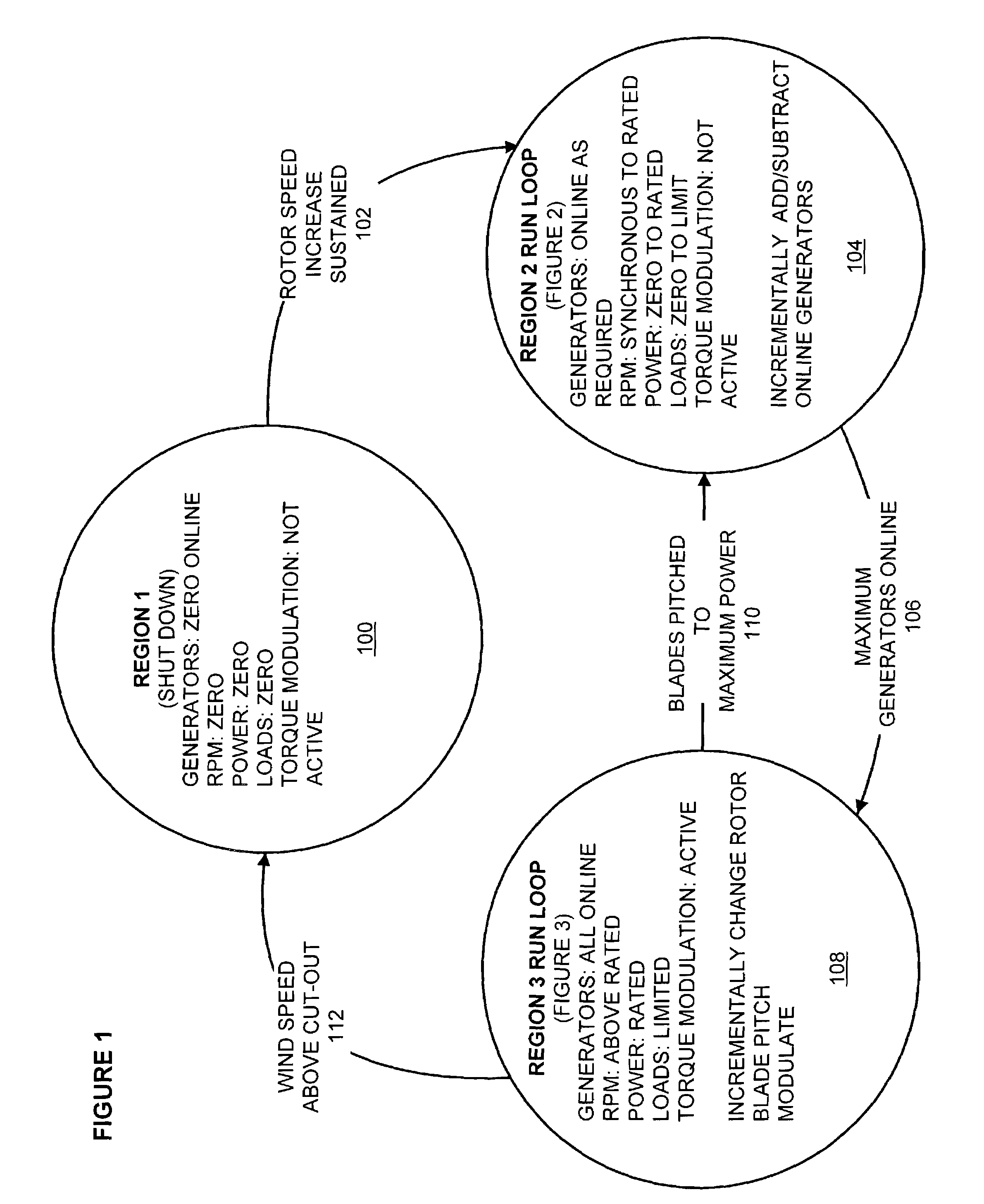
[0023]This invention applies principally to wind and ocean current turbine generators employing the Distributed Generation Drivetrain (DGD) powertrain described in U.S. Pat. No. 6,304,002 and using a number of rotating electrical machines, either motors or generators. Preferably the number of electrical machines is five or more. The large number of machines is significant because it reduces the power rating of any single electrical machine to below 20% of the total system rating, allowing for enhanced use of the controls taught by this invention.

[0024]As illustrated by the chart of FIG. 4, for a wind turbine system, there are three principal wind speed regions. The turbine is designed to operate differently in each region. In very low wind speeds (below approximately 3–5 m / s), Region 1 operation controls do not allow the turbine to generate any electricity, as the wind energy resource is not sufficient. As winds increase into Region 2 operation, the rotor begins to produce power. It...


PUM


Abstract

A controller for high torque, low RPM wind turbines and ocean current turbines. The turbine consists of a large, input power shaft-mounted, rotating bull-gear with stationary powertrains mounted around its periphery. The gear teeth on the bull-gear rotate past the teeth on pinions, causing the pinions to turn and delivering power to each smaller powertrain. A controller regulates torque experienced by each powertrain to assure that torques are balanced between generators at any given system load. The control method comprises the programmatically continuously looping steps of measuring a system parameter to be controlled, such as torque and/or speed, selecting the optimal number of generators to be connected/disconnected to a utility line, incrementally connecting or disconnecting generators to achieve the point of optimal performance, measuring the parameters, such as current and/or voltage, of the connected generators and adjusting the generator parameters to fine tune the system for optimal performance.

Description

CROSS-REFERENCE TO RELATED APPLICATIONS[0001]This application is a continuation-in-part of US Provisional Patent Application No. 60 / 313,725 Filed: Aug. 21, 2001, and is related to U.S. Pat. No. 6,731,017 entitled “Improved Distributed Powertrain That Increases Electric Power Generator Density” filed Aug. 7, 2002, and granted May 4, 2004, both of which are incorporated herein by reference.BACKGROUND OF THE INVENTION[0002]1. Field of the Invention[0003]This invention relates to electrical rotating machines connected to a common shaft and more particularly to a method of controlling a number of mechanically coupled electrical rotating machines such as wind turbines and ocean current turbines.[0004]2. Description of the Prior Art[0005]Many electric power-generating devices, such as wind turbines and ocean current turbines, benefit from economies of scale, yielding lower costs for generated electricity with larger power generation per unit. This increase in power is often accompanied by ...

Claims


Application Information

Patent Timeline
Patent Type & Authority Patents(United States)
IPC IPC(8): H02P9/04F03D7/04F03D11/02
CPCF03D7/043F03D11/02F05B2210/16F05B2240/2021Y02E10/723F05B2270/20F05B2270/327F05B2270/335Y02E10/722F05B2240/40F03D9/25F03D15/00F03D15/10Y02E10/72
Inventor HOWES, LAWRENCE H.MIKHAIL, AMIR S.DEANE, GEOFF F.
Owner UNITED TECH CORP
Why Eureka
Try Eureka