Discharge lamp with bulb fixture arrangement and method for manufacturing the same

Inactive Publication Date: 2006-02-21
GENERAL ELECTRIC CO
View PDF10 Cites 6 Cited by
  • Summary
  • Abstract
  • Description
  • Claims
  • Application Information

AI Technical Summary

Benefits of technology

[0009]In an exemplary embodiment of another aspect of the present invention, there is provided a method for manufacturing a discharge lamp. The method is applicable for such discharge lamps, which comprise a discharge vessel sealed in a tubular envelope, and a lamp base covering an end part of the envelope. Such lamps also have fixing means for providing an essentially rigid fixing of the envelope to the lamp base, where the fixing means comprises a metal clamp ring surrounding a part of the envelope external to the lamp base. The method comprises the provision of a space between the clamp ring and the envelope and the provision of a hot-melt plastic lining in the space between the clamp ring and the envelope. In the method, the plastic lining is melted and substantially completely fills the space between the clamp ring and the envelope, providing a stable mechanical connection between the clamp ring and the envelope.
[0011]The hot-melt plastic lining between the clamp ring ensures a stable and substantially deflection-free support of the lamp envelope. With a suitable choice of material, the plastic lining can take up the mechanical stress between the clamp ring and the envelope as the latter expands due to the high operating temperature of the discharge chamber. At the same time, an advantageously stable support is provided, firstly because the envelope is held close to its centre of gravity, secondly because the envelope is held between the two sealed portions, so the mechanical stress—particularly the bending stress—on the sealed portions is low. Since the plastic lining completely fills the space between the clamp ring and the envelope, practically no deflection occurs as a result of a relative movement between the clamp ring and the envelope. As a further advantage, the suggested fixation method requires only a very small amount of a suitably heat resistant hot-melt plastic material. The clamp ring itself can serve as the metal component for a HF induced heating of the plastic lining, and no additional elements are needed in the discharge lamp structure.

Problems solved by technology

The problem with this fixing method is that the envelope inevitably develops stress around the indented portions at the sealing to the discharge vessel, and tends to break at these indented portions due to excessive vibration and similar mechanical loads.
Though the above method also largely eliminates the cracking of the envelope at the indented sealing portions, other problems remain.
However, these undulations also allow a certain degree of deflection of the envelope, particularly under shock and vibration during normal use of the lamp, for example in an automotive headlight.
This deflection of the envelope may cause a degradation of the optical parameters of the headlight.

Method used


Image

  • Discharge lamp with bulb fixture arrangement and method for manufacturing the same
  • Discharge lamp with bulb fixture arrangement and method for manufacturing the same
  • Discharge lamp with bulb fixture arrangement and method for manufacturing the same

Examples


Embodiment Construction

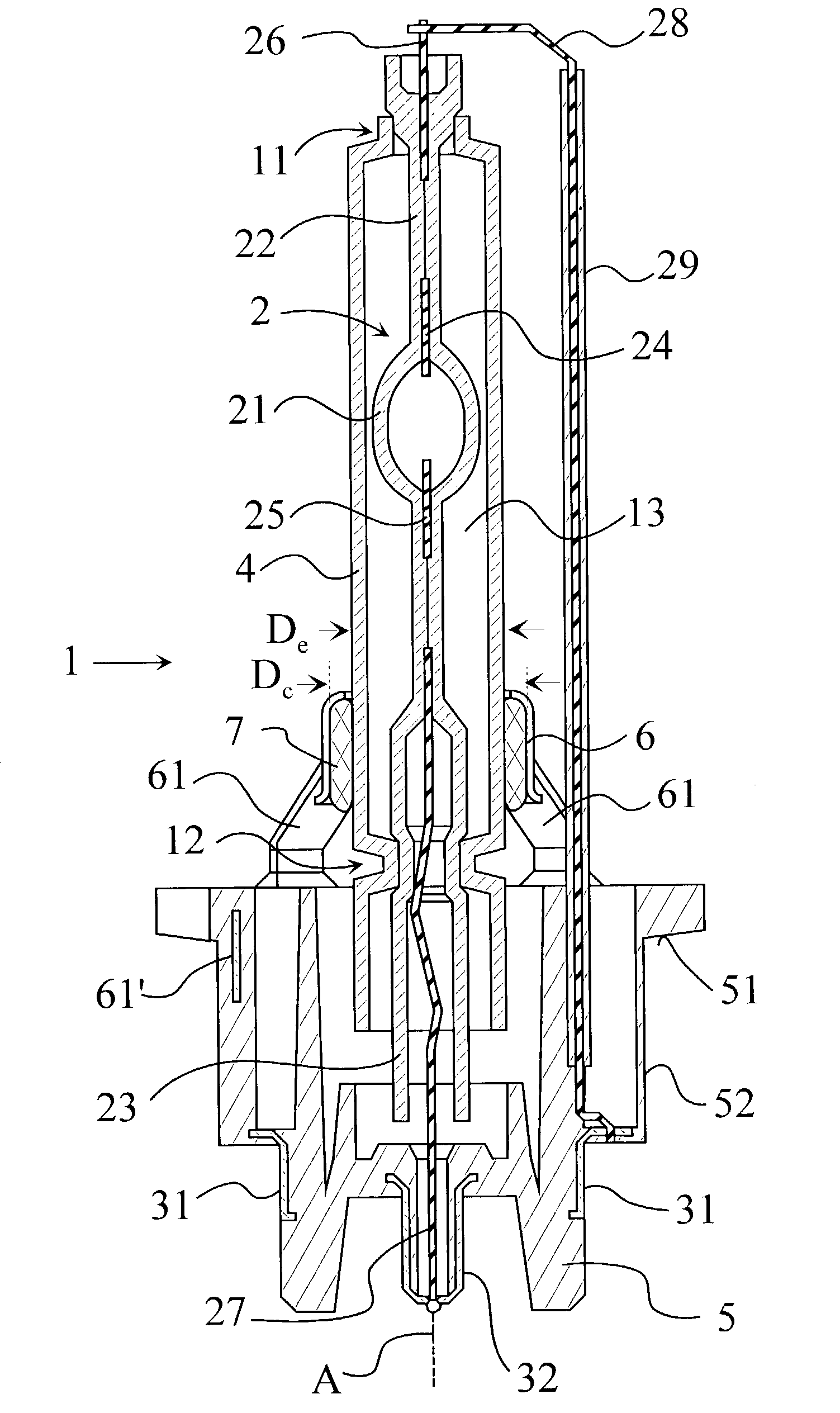
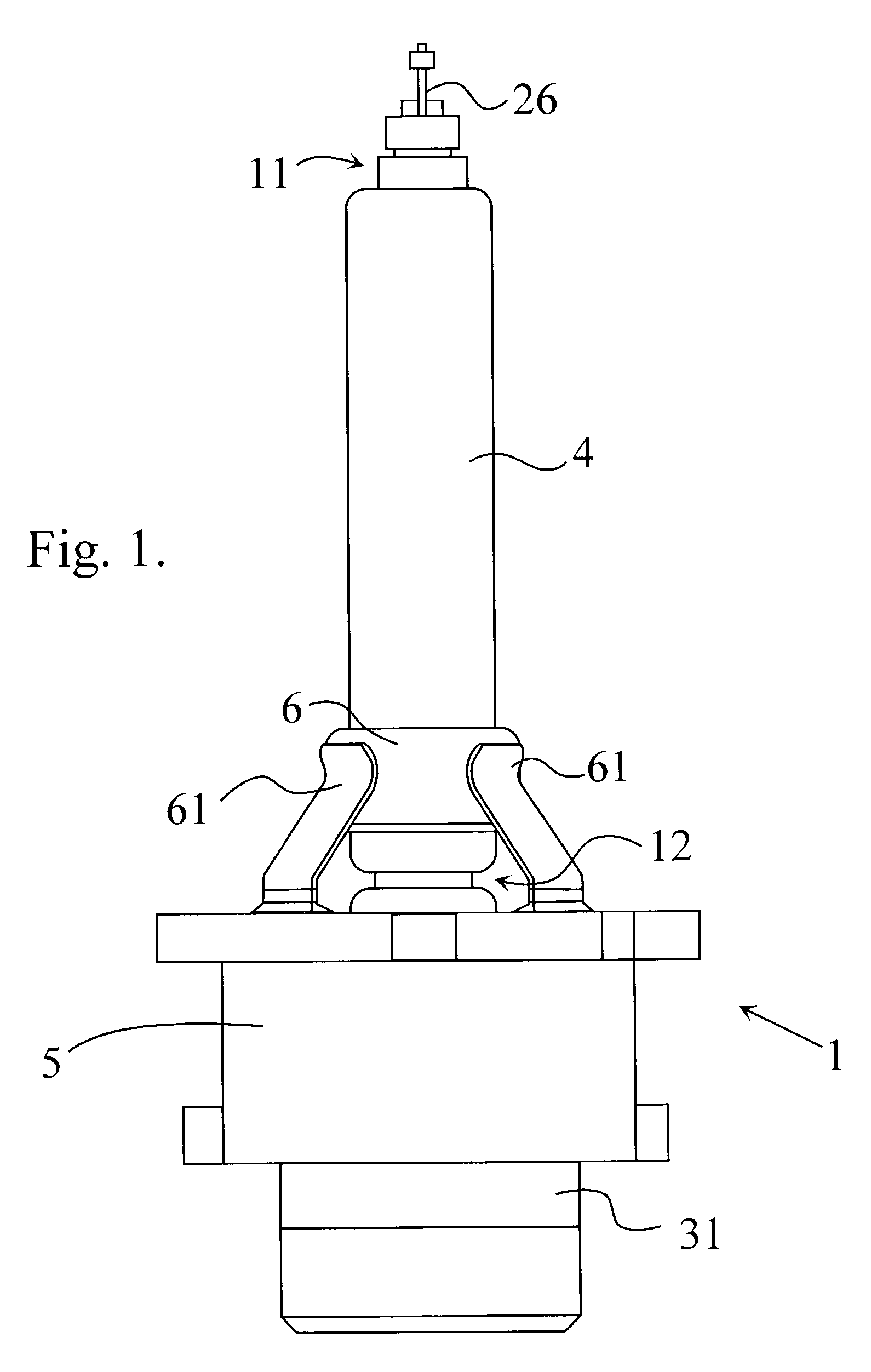
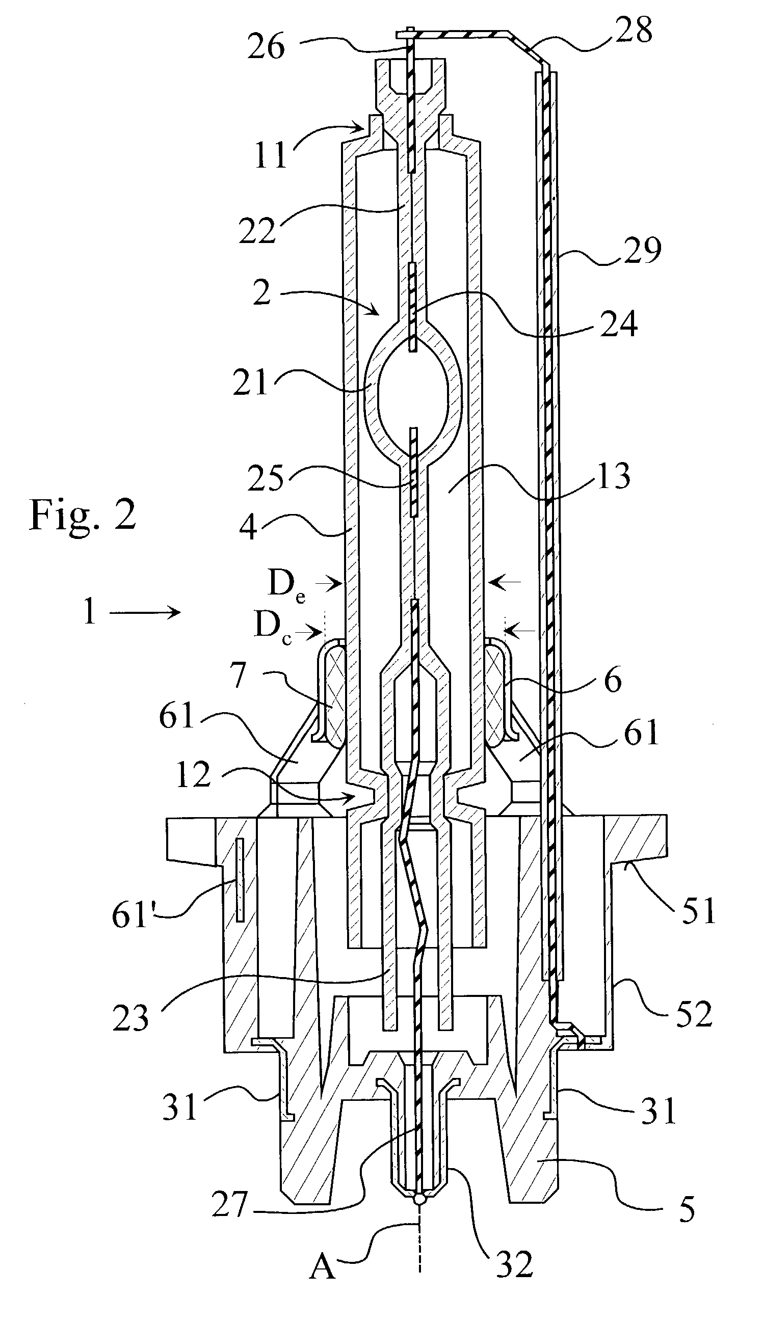
[0017]Referring now to FIGS. 1 to 2, there is shown a high pressure discharge lamp 1 for automotive purposes. This is a so called D2 type lamp, which has a sealed discharge vessel2. The discharge vessel 2 consists of a discharge chamber 21, and an upper end part 22 and a lower end part 23. These latter are sealed, so that a suitable high pressure gas atmosphere is maintained in the discharge chamber 21, for example a xenon atmosphere of 8–10 bar. The end parts 22 and 23 enclose electrodes 24,25 and lead wires 26,27. The lead wires 26,27 are connected to the electrodes 24,25 through molybdenum foils, in a known manner. The upper lead wire 26 connects to a first contact 31 through another connecting wire 28, while the lower lead wire 27 connects to a second contact 32 directly. The connecting wire 28 is insulated by a sheath 29, e.g a steatite tube. The contacts 31,32 are mechanically supported by the lamp base 5, which latter also supports the discharge vessel 2, as will be explained...


PUM


Abstract

A discharge lamp is disclosed, which comprises a discharge vessel sealed in a tubular envelope. The lamp has a lamp base covering an end part of the envelope, and fixing means for providing a substantially rigid fixing of the envelope to the lamp base. The fixing means comprises a metal clamp ring, which surrounds a part of the envelope external to the lamp base. A melt plastic lining is provided between the clamp ring and the envelope. The melt plastic lining substantially completely fills a space between the envelope and the clamp ring.A method is also provided for manufacturing a discharge lamp as above. The method comprises the steps of providing a space between the clamp ring and the envelope, and providing a hot-melt plastic lining in the space between the clamp ring and the envelope. Subsequently, the plastic lining is melted, and substantially completely fills the space between the clamp ring and the envelope, establishing a tight and stable mechanical connection between the clamp ring and the envelope.

Description

BACKGROUND OF THE INVENTION[0001]This invention relates to a discharge lamp, particularly a high pressure automotive headlight discharge lamp with an arrangement for fixing an envelope of the lamp to a lamp base. The invention further relates to a method for manufacturing such a discharge lamp.[0002]A wide variety of automotive high pressure discharge lamps are known in the art. These lamps normally comprise a relatively small discharge vessel surrounded by a larger envelope. The envelope is sealed around the discharge vessel, creating a monolithic discharge vessel-envelope assembly. The light of the lamp is generated by a discharge arc between two electrodes, producing a small light spot with very high luminous intensity. The light spot of the lamp is subject to strict positioning tolerances in order to keep the prescribed optical parameters of the headlight, into which the discharge lamp is installed. The light spot of the discharge vessel is positioned by adjusting the complete d...

Claims


Application Information

Patent Timeline
IPC IPC(8): H01J5/48H01J5/50F21V19/00F21S8/10F21Y101/00H01J5/54H01J5/58H01J5/60H01J9/24H01J23/26H01J61/34H01J61/86
CPCH01J5/54H01J5/58H01J61/86H01J61/34H01J5/60H01J61/36
Inventor MUDRA, ISTVANBELLA, SZABOLCSGARAMVOLGYI, PAL
Owner GENERAL ELECTRIC CO
Why Eureka
Try Eureka