Method and apparatus for measuring waveforms and wavelengths of optical signals

a technology of optical signals and waveforms, applied in the field of measuring optical signals, can solve the problems of inability to meet the requirements of the range of wavelengths that can be satisfactorily measured, inability to measure the characteristics of measured signals simultaneously, and inability to achieve the full signal strength of the measurement. achieve the effect of measuring wave shapes and wavelengths

Inactive Publication Date: 2006-02-21
AGILENT TECH INC
View PDF7 Cites 7 Cited by
  • Summary
  • Abstract
  • Description
  • Claims
  • Application Information

AI Technical Summary

Benefits of technology

[0012]The present invention provides a method and apparatus for measuring characteristics of a single-wavelength optical signal constituting part of a wavelength division multiplexed (WDM) optical signal. The WDM optical signal is adjustably diffracted to select the single-wavelength optical signal. An optical-to-electrical conversion is performed. An electrical sampling signal representing the selected single-wavelength optical signal is generated by one of (a) optically sampling the selected single-wavelength optical signal to generate an optical sampling signal on which the optical-to-electrical conversion is performed, and (b) electrically sampling an electrical signal generated by performing the optical-to-electrical conversion on the selected single-wavelength optical signal. This provides for measuring wave shapes and wavelengths of optical signals of different wavelengths in a WDM system efficiently and economically, while retaining substantially the full signal strength of each individual optical signal that is being measured.

Problems solved by technology

Due to the nature of optical signals, and in particular the extremely high information rates contained in the signals, previous techniques for performing such measurements are undesirably limited.
A principal limitation is that measurements in the frequency domain and measurements in the time domain are performed separately, so that the measured signal characteristics lack simultaneity.
There are also limitations with respect to the ranges of wavelengths that can be satisfactorily measured, and limitations in the optical power available for measuring the light signal as it is being processed by the measuring equipment.
Unfortunately, this results in limitations in the wavelength range that can be effectively measured, and also results in significant reductions in the resulting optical power of the final converted optical signal.
However, not all WDM signals require such expensive and powerful analytical tools, in part because the large amounts of information in such WDM signals may be distributed across a large number of separate wavelength divisions.
Solutions to these problems have been long sought but prior developments have not taught or suggested any solutions and, thus, solutions to these problems have long been elusive.

Method used


Image

  • Method and apparatus for measuring waveforms and wavelengths of optical signals
  • Method and apparatus for measuring waveforms and wavelengths of optical signals
  • Method and apparatus for measuring waveforms and wavelengths of optical signals

Examples


second embodiment

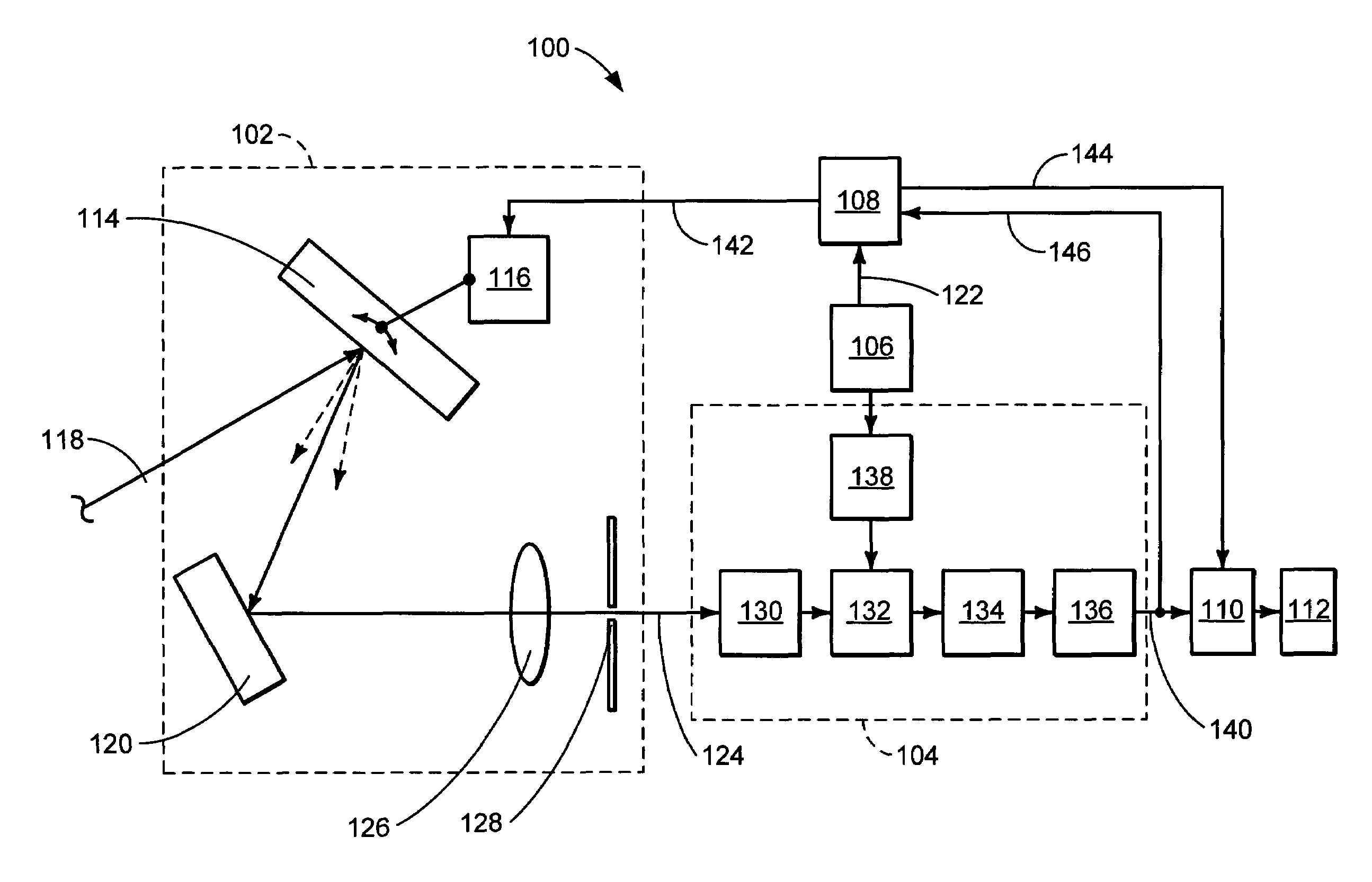
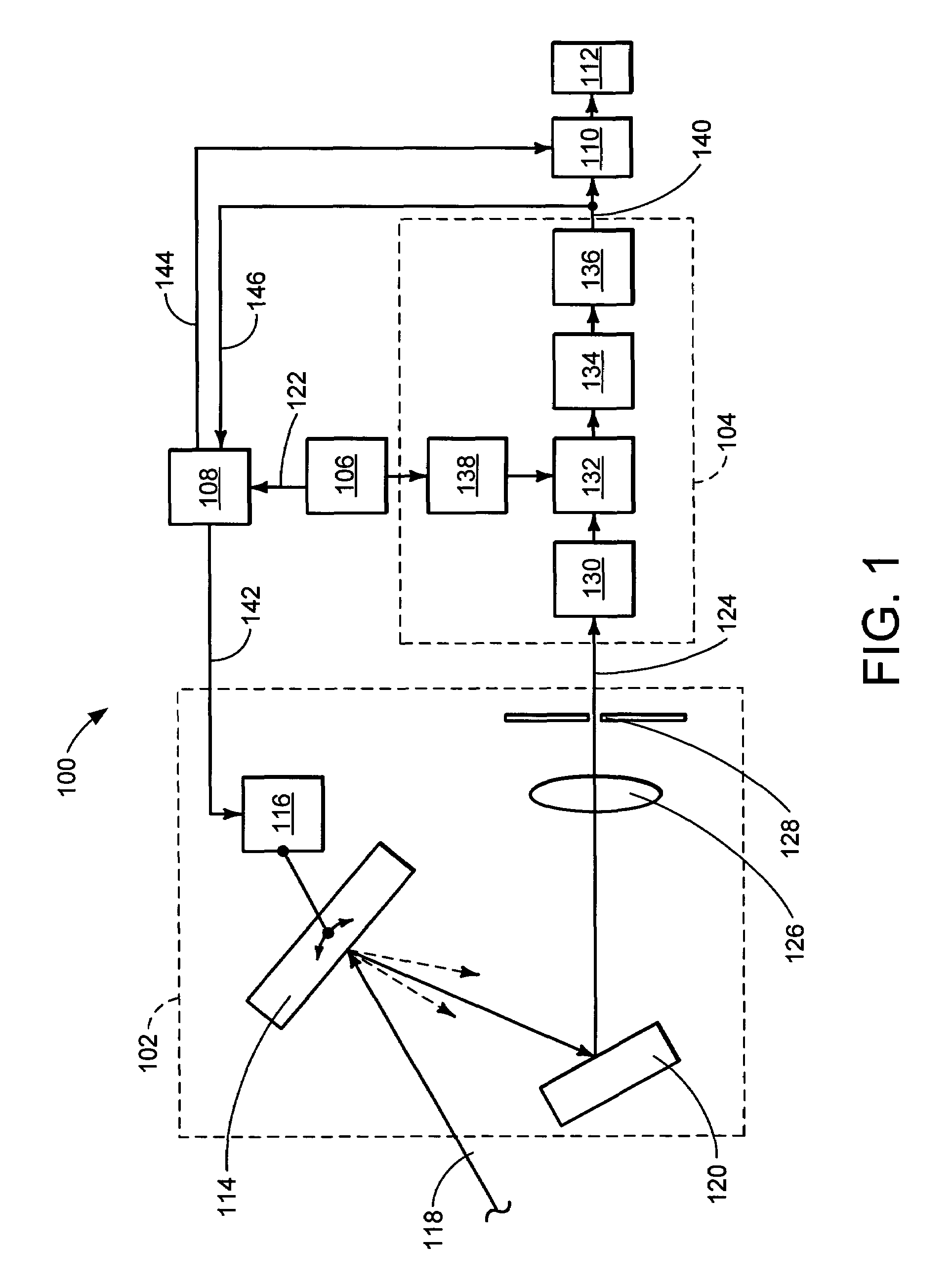
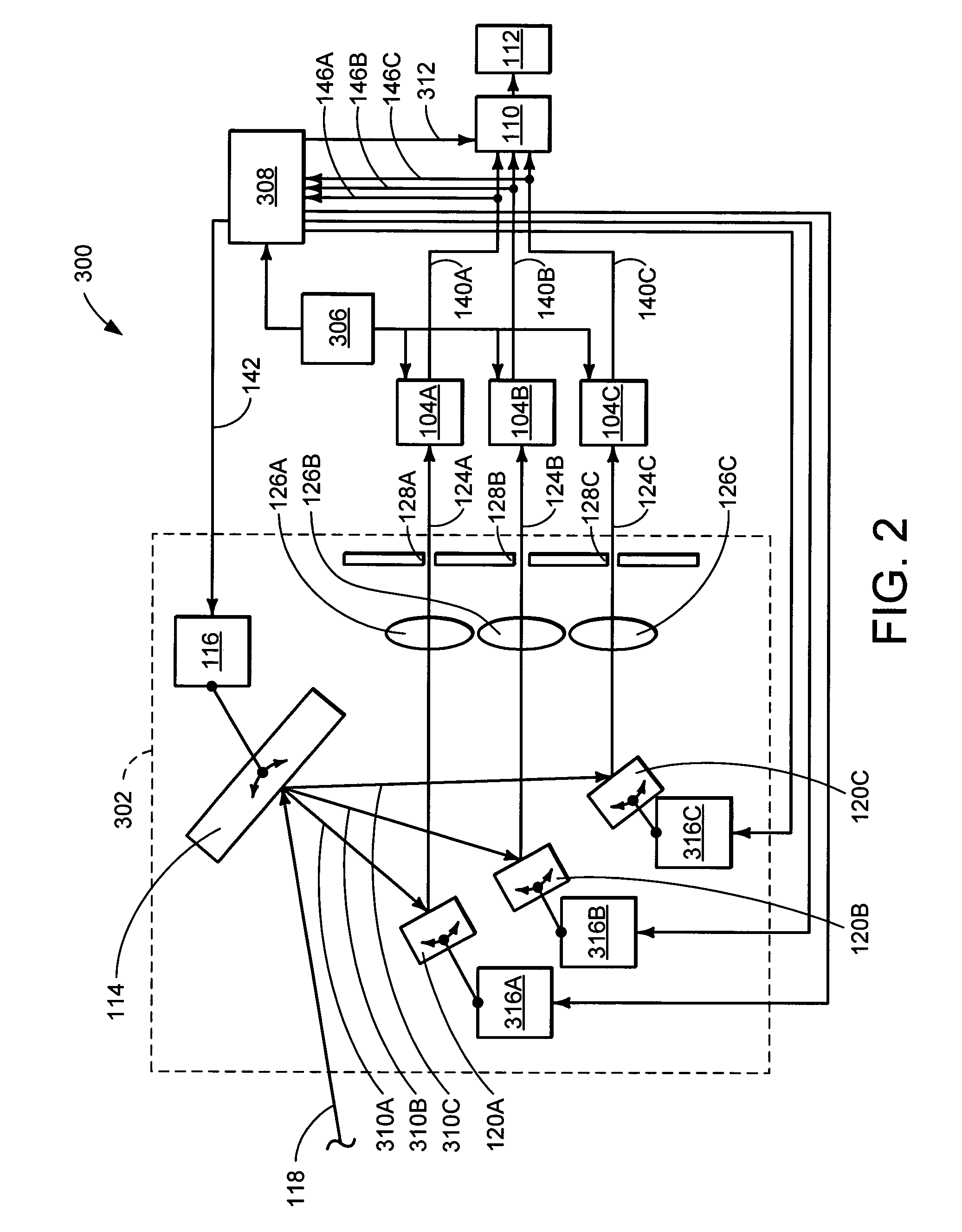
[0039]Referring now to FIG. 2, therein is shown a schematic block diagram of a waveform measuring device 300 constituting the present invention.

[0040]The waveform measuring device 300 includes a wavelength selecting module that selects multiple single-wavelength optical signals and directs them individually to corresponding sampling modules, so that the wavelength selecting functions and the optical sampling functions are each operationally connected in series. Thus, the waveform measuring device 300 includes a wavelength selecting module 302 that extracts from the WDM optical signal 118 a number of single-wavelength optical signals 124A, 124B, and 124C having respective wavelengths. The waveform measuring device 300 also includes a corresponding number of sampling modules 104A, 104B, and 104C, each substantially the same in construction and function as the sampling module 104 (FIG.1). The sampling modules 104A, 104B, and 104C sample and detect the selected single-wavelength optical...

third embodiment

[0046]Referring now to FIG. 4, therein is shown a schematic block diagram of a waveform measuring device 400 constituting the present invention. In this embodiment, the wavelength selection function and the sampling function occur together in a wavelength isolating / sampling module 420. The wavelength isolating / sampling module 420 thus functions as both a wavelength selector and a sampler, in which sampling is performed optically immediately following the wavelength selection. The sampled optical signal is then transmitted to an optical to electrical conversion module 422 that converts the sampled wavelength output, all under the control of a control circuit 406.

[0047]To sample the single-wavelength optical signal selected by the diffraction grating 114, a reflector 408 is positioned to receive the selected single-wavelength optical signal from the diffraction grating 114. The reflector 408 has a saturable light absorbing material 410 on its surface. The reflectivity of the reflector...


PUM

PropertyMeasurementUnit
wavelength rangeaaaaaaaaaa
single-wavelengthaaaaaaaaaa
timeaaaaaaaaaa

Abstract

A method and apparatus for measuring characteristics of a single-wavelength optical signal constituting part of a wavelength division multiplexed (WDM) optical signal is provided. The WDM optical signal is adjustably diffracted to select the single-wavelength optical signal. An optical-to-electrical conversion is performed. An electrical sampling signal representing the selected single-wavelength optical signal is generated by one of (a) optically sampling the selected single-wavelength optical signal to generate an optical sampling signal on which the optical-to-electrical conversion is performed, and (b) electrically sampling an electrical signal generated by performing the optical-to-electrical conversion on the selected single-wavelength optical signal.

Description

TECHNICAL FIELD[0001]The present invention relates generally to the measurement of optical signals, and more particularly to a method and apparatus for measuring optical signals together in time and frequency domains.BACKGROUND ART[0002]In recent years, largely due to the increasing popularity of the Internet, there has been an abrupt expansion in the volume of communications. This has stimulated improved methods for increasing the capacity of communications channels. One such method is time division multiplexing (“TDM”), in which information from several communication signals can share the same transmission channel. To do so, the bits for each signal are assigned to individual time slots or time periods that repeat or rotate so quickly that each signal has enough of the time slots to transmit all of its own information. When the information stream is received, the individual information signals are then separated based upon the assignments of each signal to its own repeating time p...

Claims


Application Information

Patent Timeline
Patent Type & Authority Patents(United States)
IPC IPC(8): G01J11/00G01J3/30G01J3/18G02F1/35G02F1/37H04B10/00H04B10/07H04J14/02
CPCG01J3/1804H04J14/02G01J2003/1866
Inventor KANEKO, YASUHISA
Owner AGILENT TECH INC
Why Eureka
Try Eureka