
Communication system transmitting encoded signal using block lengths with multiple integral relationship

a communication system and block length technology, applied in the field of communication systems, can solve the problems of limiting the frame size that the system could use, changing the transmission rate, and the receiver performing a fairly complex and time-consuming synchronization operation, so as to achieve the overall rate of reliable information transmitted through a fading channel, the effect of constant channel transmission rate and easy change of information rate and block length

Inactive Publication Date: 2006-02-21
SONY CORP
View PDF7 Cites 81 Cited by
  • Summary
  • Abstract
  • Description
  • Claims
  • Application Information

AI Technical Summary

Benefits of technology

[0014]It is an objective of the present invention to provide a transmission system, transmitter, receiver, and method capable of varying block length depending on the present conditions of the transmission link, without requiring complex resynchronization operations, or symbol stuffing or long frames to maintain a constant transmission rate.
[0044]Also, a constant channel transmission rate will be maintained even when the block length changes. Therefore, a receiver that operates according to this method receives a signal with a fixed transmission rate. Since the receiver does not need to be adjustable for varying transmission rates caused by mismatches in block length, the receiver can be less complex and less costly. Also, complex and time consuming synchronization operations can be reduced.

Problems solved by technology

However, a change in block length changes the transmission rate.
When the receiver does not find particular information where expected, the receiver will perform a fairly complex and time consuming synchronization operation.
However, it is desirable to transmit only useful data, rather than such redundant symbols.
However, this would greatly limit frame sizes that the system could use.
Moreover, the system would require a great deal of memory to handle such large frames.

Method used


Image

  • Communication system transmitting encoded signal using block lengths with multiple integral relationship
  • Communication system transmitting encoded signal using block lengths with multiple integral relationship
  • Communication system transmitting encoded signal using block lengths with multiple integral relationship

Examples


first embodiment

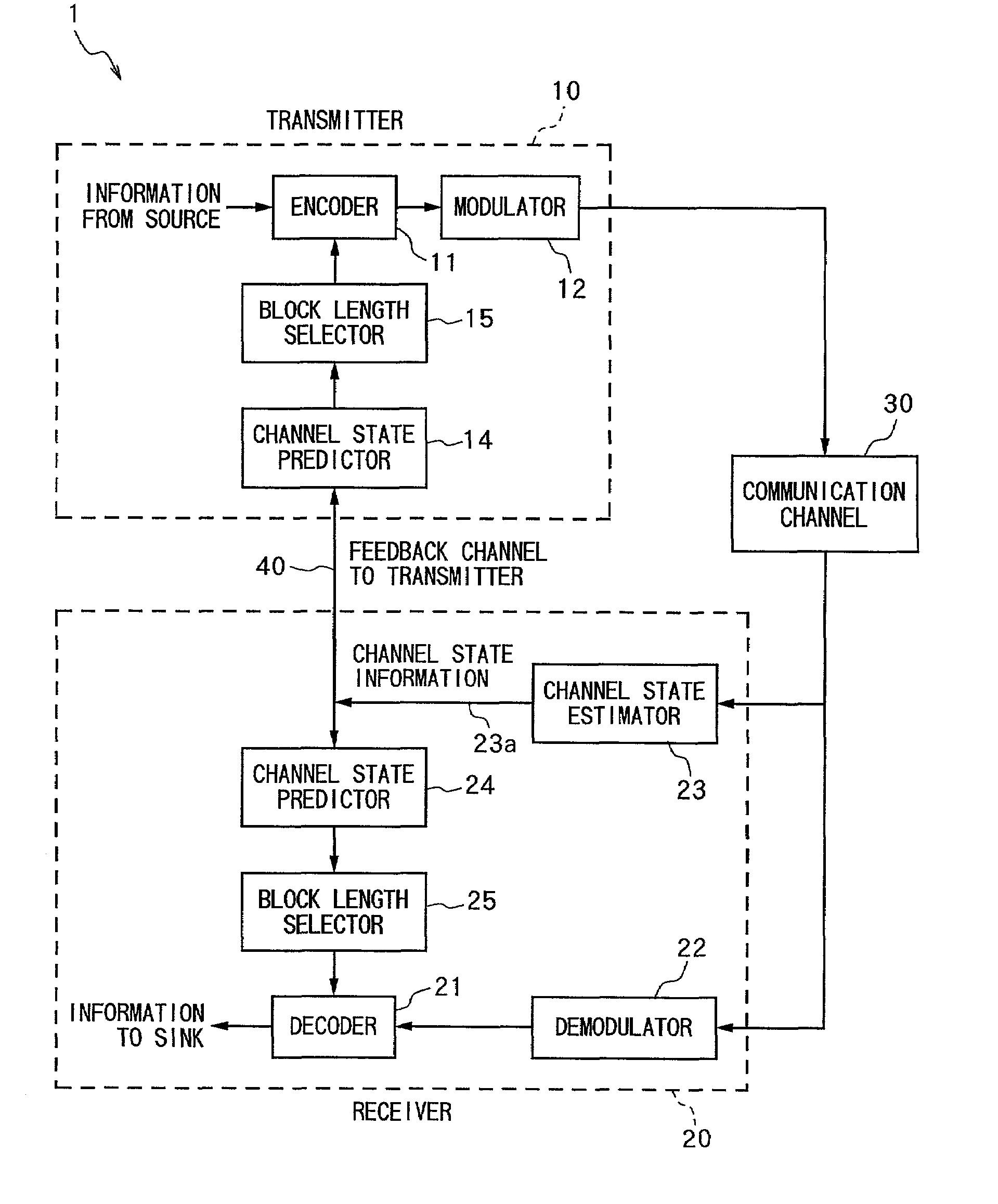
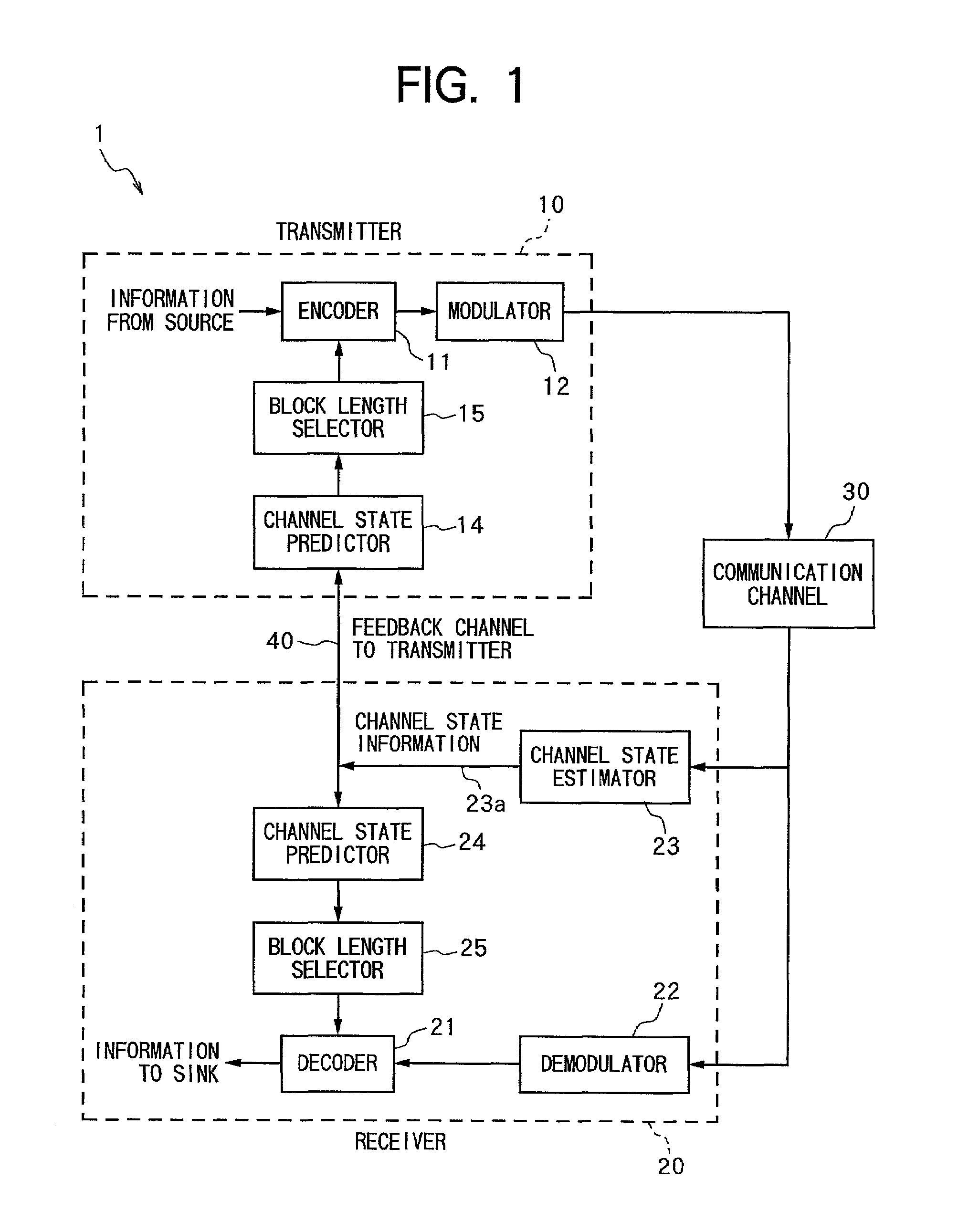
[0054]FIG. 1 is a functional block diagram showing a transmission system 1 according to a The transmission system 1 includes a transmitter 10 and a receiver 20. The transmitter 10 transmits information to the receiver 20 across a communication channel 30, which includes noise and fading.

[0055]The transmitter 10 includes an encoder 11, a modulator 12, a channel state predictor 14, and a block length selector 15. The encoder 11 receives information from a source, and encodes the information. The encoder 11 outputs the source information in encoded form to the modulator 12. The modulator 12 modulates the encoded signal from a base band up to a carrier band and transmits it across the communication channel 30.

[0056]The receiver 20 includes a decoder 21, a demodulator 22, a channel state estimator 23, a channel state predictor 24, and a block length selector 25. The demodulator 22 receives and demodulates the signal from the transmitter 10 from the carrier signal back down to the base b...

second embodiment

[0093]FIG. 7 shows a broadcasting system 101 according to the present invention. The broadcasting system 101 includes a broadcast transmitter 110, a monitor receiver 125, and a plurality of broadcast receivers 120. The broadcast transmitter 110 transmits a signal to the monitor receiver 125 and the broadcast receivers 120 across a communication channel 130 with noise and fading. Although only a single broadcast receiver 120 is shown in FIG. 7, the other broadcast receivers 120 of the broadcasting system 101 have the same configuration, so their explanation will be omitted.

[0094]The monitor receiver 125 includes a code schedule producer 126 that performs the functions of predicting the channel state and selecting block length described for the channel state estimator 23, the channel state predictors 14, 24, and block length selectors 15, 25 of the first embodiment. The code schedule producer 126 prepares a schedule of codes, which includes block length and information rate, and trans...


PUM


Abstract

A communication system for performing transmission and reception of a signal over a communication channel assesses a state of the communication channel and produces channel state information accordingly. A block length selector selects block lengths that are dependent on the channel state information and that are selected from a group of block lengths having an integral multiple relationship to produce a schedule of block lengths. Encoding and decoding is performed based on the schedule of block lengths.

Description

BACKGROUND OF THE INVENTION[0001]1. Field of the Invention[0002]The present invention relates to a communication system transmitting an encoded signal across a channel with noise and fading.[0003]2. Description of the Related Art[0004]A communication system includes a transmitter and a receiver connected by a communication channel. In a wireless communication system, especially a mobile wireless communication system, the condition of the communication channel can change rapidly. The capacity of the channel varies with the channel condition. That is, the channel can hold more information when channel conditions are good, and less information when conditions are bad. If the transmitter and receiver are designed with parameters fixed to levels that assume less than optimal channel conditions, then they will not use the full capacity of the communication channel when the channel conditions approach the optimum channel conditions.[0005]For example, radio waves propagate between the trans...

Claims


Application Information

Patent Timeline
Patent Type & Authority Patents(United States)
IPC IPC(8): H04B14/04H04B1/04H04B7/26H04L1/00H04L29/06
CPCH04L1/0007H04L1/0019H04L1/0026
Inventor MORELOS-ZARAGOZA, ROBERTSWARTS, FRANCIS
Owner SONY CORP
Learn More