Telecommunications receiver and a transmitter

a receiver and transmitter technology, applied in the field of telecommunications receivers and telecommunications transmitters, can solve problems such as canceling error components of output signals, and achieve the effect of improving carrier suppression

Active Publication Date: 2006-02-21
LUCENT TECH INC
View PDF9 Cites 11 Cited by
  • Summary
  • Abstract
  • Description
  • Claims
  • Application Information

AI Technical Summary

Benefits of technology

[0008]Embodiments of receivers and transmitters in accordance with the present invention realize that two circuits of the same type, and possibly integrated on the same chip, normally behave very similarly. In these embodiments, using two IQ-mixer stages, which are operated in 180 degrees phase shift, results in the error components of the output signals being cancelled. Embodiment of the receivers and transmitters in accordance with the present invention thus preferably involve the use of two IQ-mixers of the same type in order to cancel out unwanted components of output signals. In the receivers, DC-offsets are cancelled. In the transmitters, residual carrier signals are cancelled. Also, for both transmitters and receivers, the wanted signals are added which doubles the amplitude of the output signal and leads to four times more output power, thus also giving an improved dynamic range on the output.
[0011]Embodiments of the present invention can also provide significant other advantages. As regards receiver embodiments, DC offsets are cancelled in real time, independent of the signal strength, frequency, or the level of the local oscillator (LO) input signals to the mixers. A further advantage is that any feedthrough of the local oscillator signal in the reverse direction is cancelled in the 180° power combiner at the input to the receiver.
[0012]As regards transmitter embodiments, carrier suppression is improved by cancelling out the individual residual carrier signals, e.g. residual local oscillator signals, of each IQ-mixer in the 180° combiner. Furthermore, the noisefloor, i.e. minimum signal power to be handled, is improved by 3 dB as the noise of both IQ-mixers is not correlated, but the wanted signals processed by the two mixers are correlated.
[0013]As regards further advantages of embodiments of both receivers and transmitters, device dependant effects, such temperature drifts, are fully compensated for as they are the same for the two IQ-mixers of the same type. A further advantage of receiver embodiments is that a need of the prior art to tune gain and delay differences between I and Q branches (as discussed above) is avoided.

Problems solved by technology

In these embodiments, using two IQ-mixer stages, which are operated in 180 degrees phase shift, results in the error components of the output signals being cancelled.

Method used


Image

  • Telecommunications receiver and a transmitter
  • Telecommunications receiver and a transmitter
  • Telecommunications receiver and a transmitter

Examples


embodiment 1

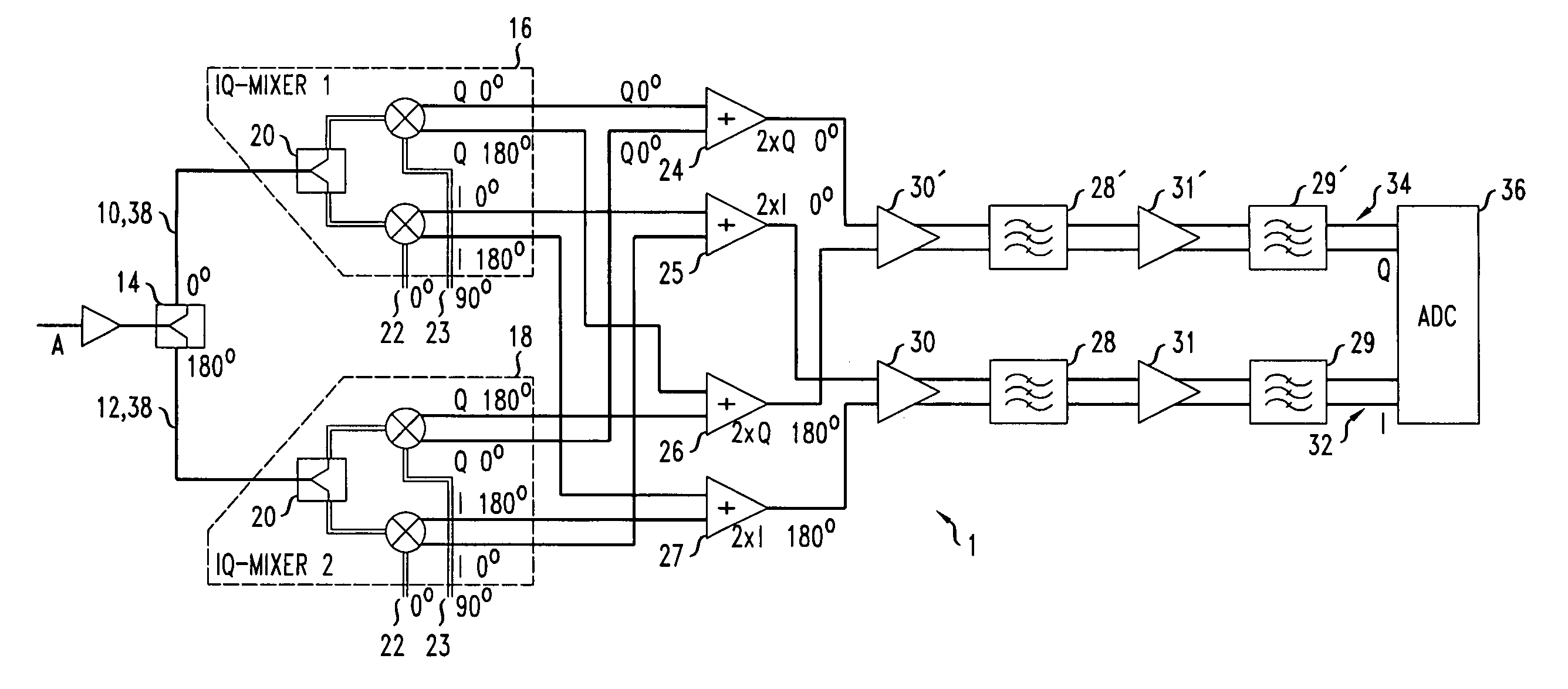
[0020]In a first receiver embodiment 1 as shown in FIG. 1, the input signal A is amplified by an amplifier DRV and split into two paths 10,12, a path 10 with no phase shift and a path 12 with a phase shift of 180 degrees. One way to achieve the phase shift is to use a 180° Hybrid 14, to ensure that the signal levels are the same for both paths 10,12.

[0021]Signals on each of the paths 10,12 are then processed by a respective IQ mixer 16,18, each of which uses two LO-signals, one 22 with 0° phase shift and one 23 with 90° phase shift. The IQ-mixers 16,18 for both paths 10,12 are identical in structure. Each mixer 16,18 incorporates a splitter 20 and signal inputs 22,23 from a local oscillator (LO, not shown). Both IQ-mixers are implemented on the same integrated circuit chip. The length of the connectors 38 from the 180° Hybrid 14 to each splitter 20 is the same.

[0022]Due to imperfections of the IQ-mixers 16,18 an unwanted DC offset appears at the outputs of the IQ-mixers 16,18. Each ...

embodiment 201

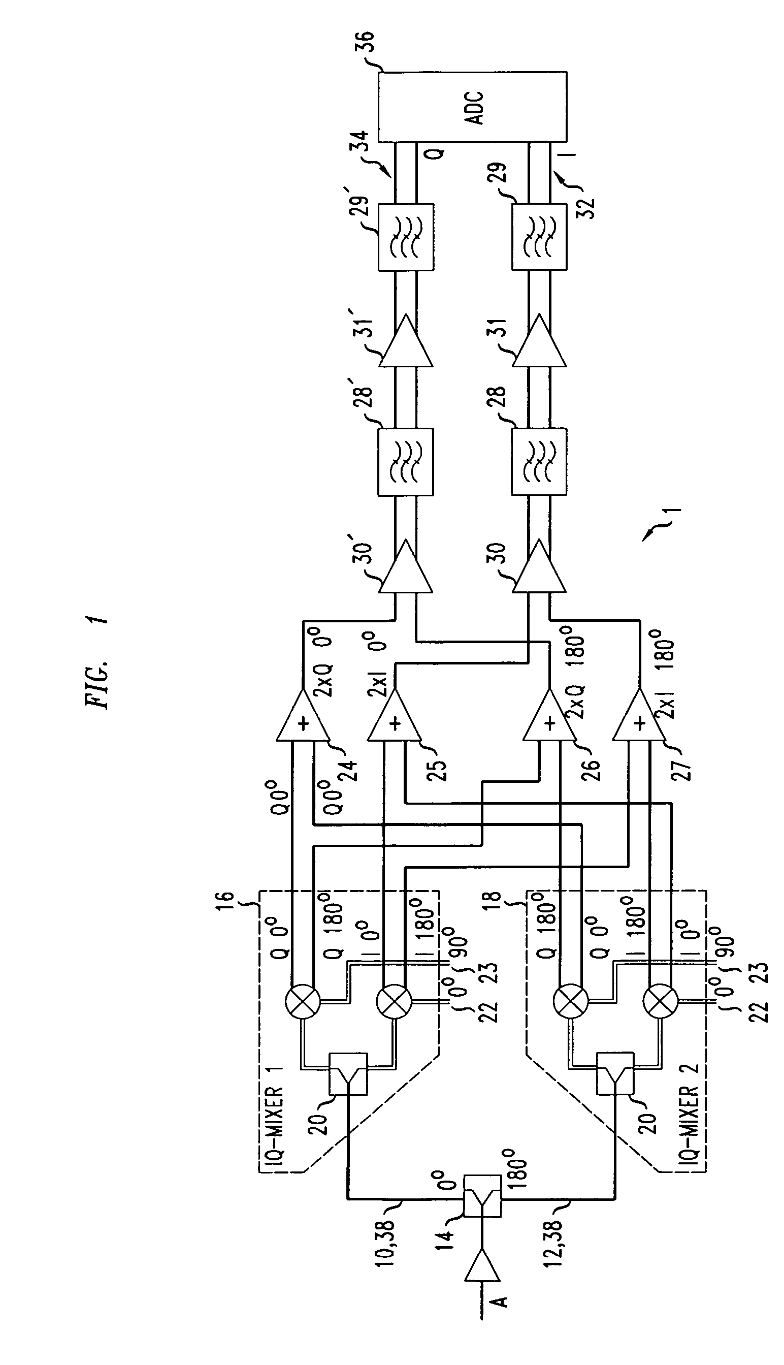
[0027]A second receiver embodiment 201 is shown in FIG. 2. This receiver has essentially the same structure and function as the receiver shown in FIG. 1 except that the input signal A′ is directed to one path 210 (so there is no 180° Hybrid). A reference signal B which is zero is provided instead to the other path 212 so that the second IQ-mixer 218 is used to generate a reference DC offset which is then used for cancellation purposes as in the receiver in FIG. 1. As cancellation of effects which are dependent of the input signal level are not taken into account, the performance of this embodiment may be lower than the receiver in FIG. 1.

Other Receivers

[0028]A third receiver 301 is shown in FIG. 3. In this receiver, the I and Q signals from each IQ-mixer 316, 318 are provided as unbalanced signals to the differential variable gain amplifiers 330. Specifically, the 0° phase I component from IQ-mixer 316 and the 180° phase I component from IQ-mixer 318 are passed through a respective ...


PUM


Abstract

In a telecommunications transmitter and receiver two IQ-mixers of the same type are operated in 180 degrees phase shift. In both the transmitter and receiver, an input signal is coupled to each IQ-mixer and the output signal of the mixers are combined so as to cancel unwanted error components in each individual output signal. In the transmitter, residual carrier signals are cancelled, and in the receiver, DC-offsets are cancelled. In both, the wanted signals are added, doubling the amplitude of the resultant output signal leading to four times more output power and improved dynamic range.

Description

TECHNICAL FIELD[0001]The present invention relates to a telecommunications receiver and a telecommunications transmitter.BACKGROUND OF THE INVENTION[0002]In the field of receiver and transmitter technology for mobile telecommunications to date, only receivers incorporating fixed analog intermediate frequency (IF) stages have been found suitable for use in base stations. This is because of the large range of power levels which must be handled, and also a requirement for a low level of blocking. The range of power levels is often called the dynamic range and is usually quantified as the ratio between strongest and weakest usable power levels. Blocking is, of course, the problem of a weaker signal being drowned out by a stronger signal.[0003]Direct conversion receivers with zero or near-zero IF stages are becoming available. However they are only suitable for use in mobile user terminals but not base stations because power range and blocking requirements of mobile user terminals are mu...

Claims


Application Information

Patent Timeline
Patent Type & Authority Patents(United States)
IPC IPC(8): H04B1/00H04B1/26H03D7/00H03D3/00H04B1/30H04B7/155H04L27/20H04L27/22H04L27/36H04L27/38
CPCH04B1/30H03D3/008B05B1/22B05B17/08
Inventor FISCHER, GEORGRITTER, KAI-UWE
Owner LUCENT TECH INC
Why Eureka
Try Eureka