Electronic apparatus having radio transmitter

a technology of electronic equipment and radio transmitter, which is applied in the direction of radio transmission, transmission, transmission noise reduction, etc., can solve the problems of power noise having an adverse effect on modulation accuracy, power efficiency of power supply, increased power consumption, etc., and achieve the effect of reducing the switching noise of the power supply on the radio transmitter

Inactive Publication Date: 2006-02-21
FUJITSU LTD
View PDF16 Cites 9 Cited by
  • Summary
  • Abstract
  • Description
  • Claims
  • Application Information

AI Technical Summary

Benefits of technology

[0014]With the configuration described above, the effect of the swit

Problems solved by technology

Especially in a radio transmitter of a phase modulation type, power noise has an adverse effect on the modulation accuracy, and therefore a series regulator generating only a small noise is preferably used as the power supply of the radio transmitter.
In the case where the series regulator is used as a power supply, however, the power efficiency of the power supply is deteriorated to cause an increased power consumption.
In a computer system having built therein a radio transmitter employing a switching regulator as a power supply, however, the switching regulator 104 generates a ripple (switching) noise of a high power and frequency.
Once the ripple fre

Method used


Image

  • Electronic apparatus having radio transmitter
  • Electronic apparatus having radio transmitter
  • Electronic apparatus having radio transmitter

Examples


first embodiment

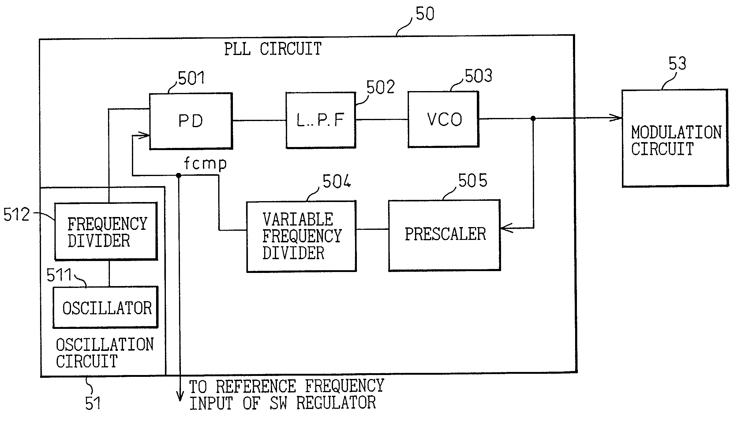
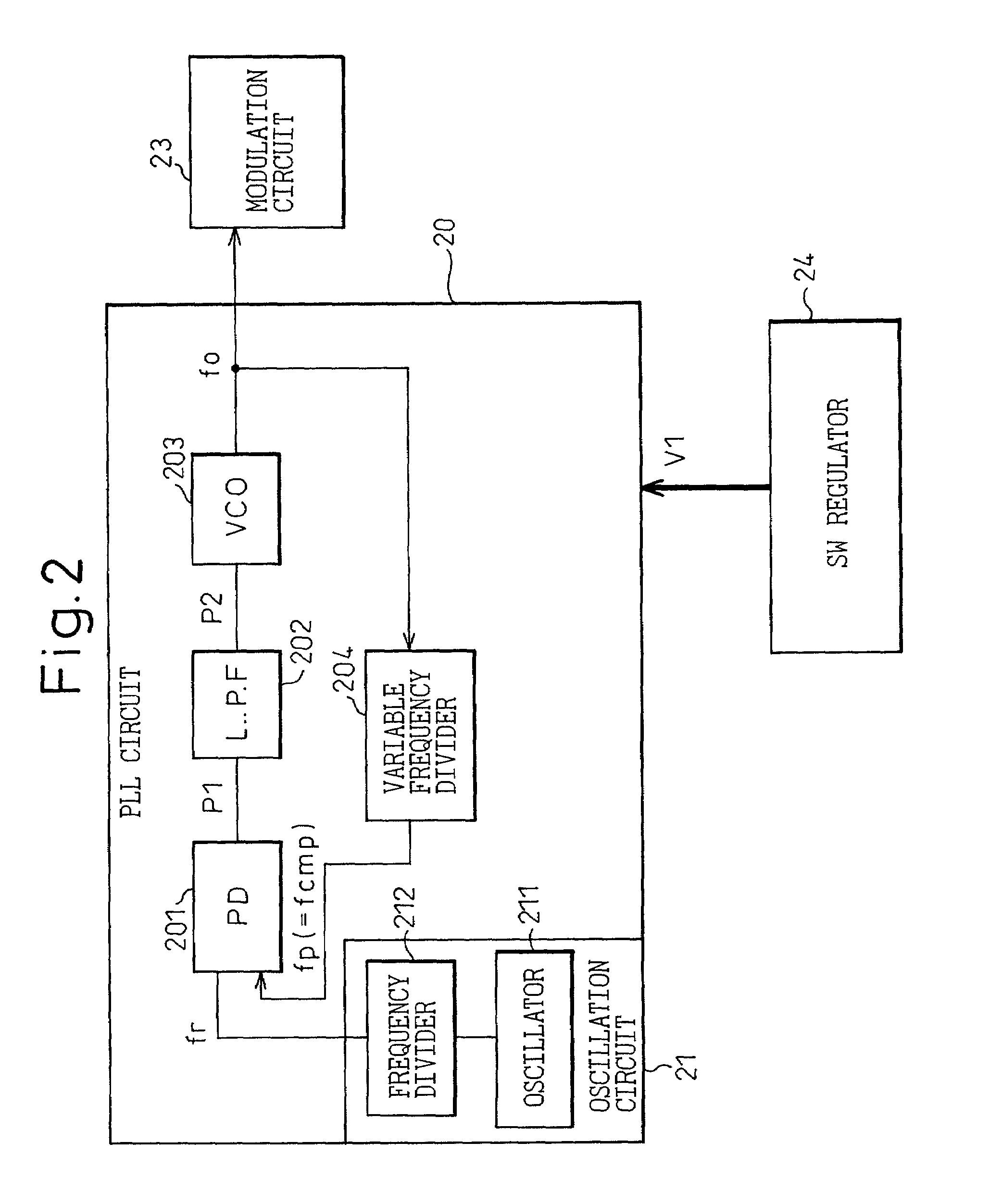
[0047]FIG. 5 is a diagram showing the PLL circuit for producing the reference frequency to be applied to the switching regulator of FIG. 1 according to the invention. The PLL circuit 50 shown in FIG. 5 has the same component elements as the PLL circuit 20 shown in FIG. 2, except that a prescaler 505 is added between the VCO and the variable frequency divider. The prescaler 505 is a preliminary frequency divider whereby the output frequency of the VCO 503, if high, is reduced to a level divisible by the variable frequency divider 504.

[0048]According to the first embodiment utilizing the feature (2) above, the comparison frequency fcmp (=300 KHz) of the PLL circuit 50 used for the radio transmitter of phase modulation type is retrieved and the output thereof is used as a reference frequency of the switching regulator.

[0049]With this configuration, the frequency of the power noise exactly coincides with the comparison frequency fcmp of the PLL, and the deterioration of the modulation a...

second embodiment

[0052] a PLL circuit is so configured that a frequency shifted from the comparison frequency of the PLL circuit to the frequency band free of deterioration of the modulation accuracy, from the comparison frequency of the PLL circuit 60, is produced as the reference frequency of the switching regulator. For this purpose, the PLL circuit 60 includes an fc-DC offset circuit 606 for adding an output voltage of the LPF 602 with a DC offset voltage corresponding to a frequency offset to the comparison frequency (fcmp) of the PLL circuit 60 in collaboration with the cutoff frequency (fc) of the LPF (low-pass filter) 602 of the PLL circuit 60, a VCO 607 providing a circuit adapted to oscillate in accordance with the result of addition in the fc-DC offset circuit 606, and a frequency divider 608. The cutoff frequency fc of the LPF602 is 5 KHz. In the case where the cutoff frequency fc of the LPF 602 is 5 KHz and the difference between the power noise frequency and the comparison frequency fc...

third embodiment

[0055] a PLL circuit 70 is configured of a frequency divider 706 for acquiring, as a reference signal of the switching regulator, a frequency equivalent to the comparison frequency of the PLL circuit 70 shifted to a frequency band where the modulation accuracy is not deteriorated. The frequency divider 706 is assumed to output a frequency signal of fcmp×½(=150 KHz).

[0056]Now, other embodiments of the invention will be described.

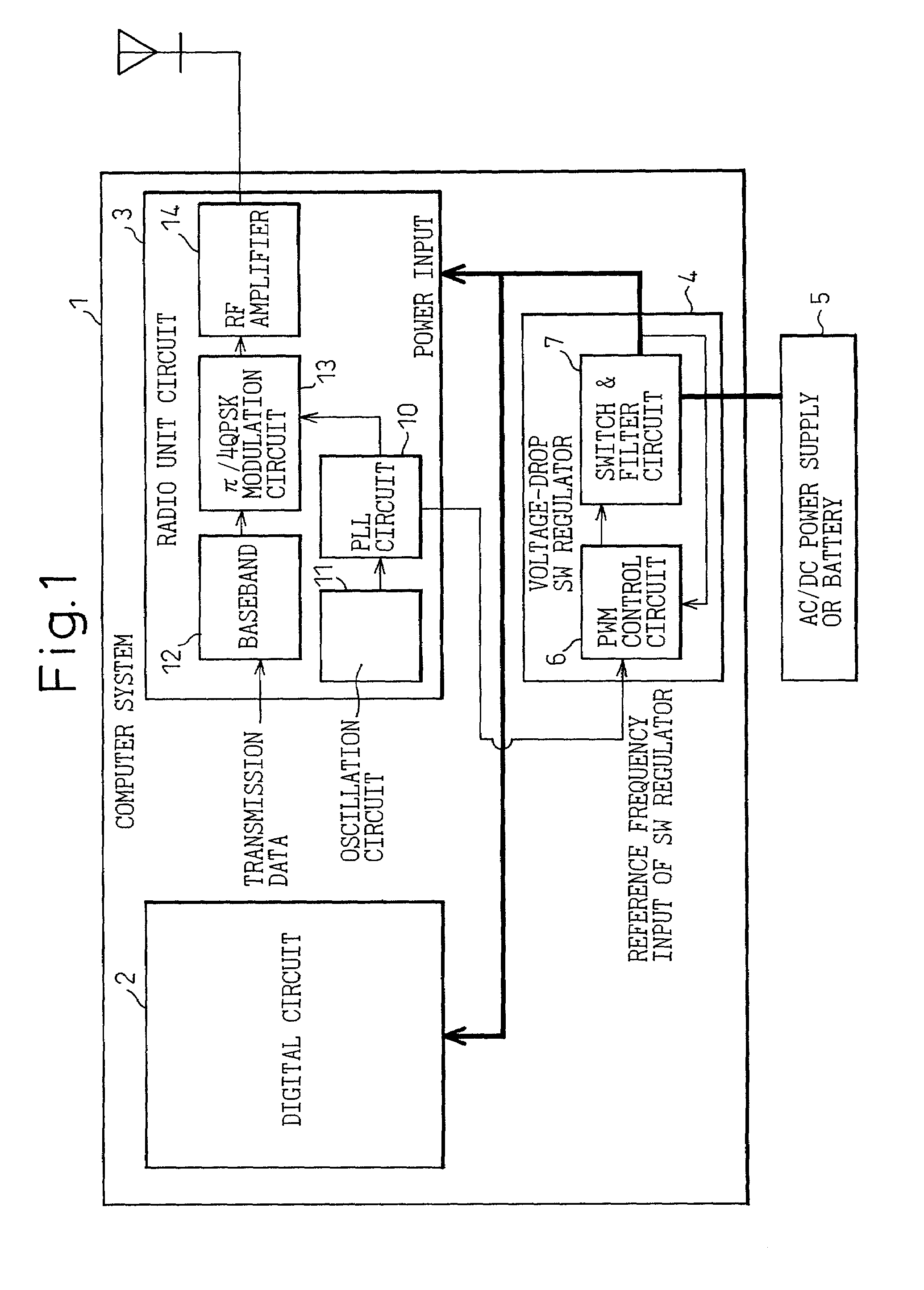
[0057]The computer system 1 shown in FIG. 1 having a radio transmitter of phase modulation type built therein further comprises a change-over switch for determining whether the radio transmission circuit 3 is to be used or not. In the case where the radio transmission circuit 3 is used, power is supplied to the circuit of the radio transmitter from the switching regulator 4, whereas in the case where the radio transmission circuit 3 is not used, power is not supplied to the circuit of the radio transmitter from the switching regulator 4 but the switching freq...


PUM


Abstract

An electronic apparatus comprising a radio transmitter is disclosed. In a computer system (1) having a radio transmission circuit (3) of a phase modulation type supplied with power from a power supply (4) of a switching type, the switching frequency of the power supply (4) is determined based on the comparison frequency for the sampling operation of a PLL circuit (10) of the radio transmitter, thereby removing the power noises generated from the switching regulator of the radio transmitter of a phase modulation type.

Description

BACKGROUND OF THE INVENTION[0001]1. Field of the Invention[0002]The present invention relates to an electronic apparatus having a radio transmitter of a phase modulation type.[0003]2. Description of the Related Art[0004]FIG. 8 is a block diagram showing a configuration of a conventional computer system having a radio transmitter built therein. In an electronic apparatus having a radio transmitter, such as a computer system 101 having the radio transmitter shown in FIG. 8 built therein, power noise, which is not of such a level as to pose any problem for a digital circuit section 102 including a low-frequency logic circuit of the computer system in the case where no radio unit is used, has a conspicuous effect on the characteristics of a radio unit circuit 103, constituting a high-frequency circuit section of the radio transmitter, in the case where the radio unit is used. Especially in a radio transmitter of a phase modulation type, power noise has an adverse effect on the modulatio...

Claims


Application Information

Patent Timeline
IPC IPC(8): H04B1/04H04B15/00
CPCH04B15/005H04B2215/069
Inventor MARUO, NOBUHIDESAOTOME, MAKOTOKOTANI, MAKOTO
Owner FUJITSU LTD
Why Eureka
Try Eureka